Operations#
The following is a table of optimization modules currently supported by Scene Optimizer, with a brief description of the functionality provided. Click on any optimization module to see detailed documentation about it.
Optimization Module |
Description |
|---|---|
Generate texture coordinates for meshes using unwrap methods with low distortion. |
|
Clips meshes to a user defined axis-aligned box. |
|
Compute and author the extent property for Meshes. If the |
|
Center mesh at centroid in canonical orientation. |
|
Reduce tessellation density for mesh prims. |
|
Convert identical meshes into instances. |
|
Dice meshes to a given regular grid or an irregular one. |
|
Set the Meters Per Unit for the stage. |
|
Identify geometry that share the same location based on a tolerance metric. |
|
Finds prims that have more than a specified number of children. |
|
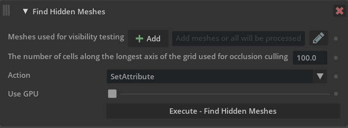
Finds meshes that are globally invisible meaning they are invisible from any camera that does not cross meshes in the scene. |
|
Replace meshes in a stage with transformed primitive geometries (sphere, cylinder, cone, or cube) if they can be fit within tolerance. |
|
Finds and removes redundant Xforms to reduce prim count. |
|
Generate normals for meshes. |
|
Generate texture coordinates for meshes using various projection methods. |
|
Makes mesh Manifold. |
|
Merge individual meshes. There are many options to control merge behavior, for example whether to merge all meshes or merge only meshes with the same material. |
|
Applies various cleanups to meshes, e.g merging vertices that are within a given tolerance apart. |
|
Run operations to optimize materials in a stage. |
|
Flatten or index primvars, or check whether they can be simplified, for example reducing from faceVarying to uniform. |
|
Merge all meshes for meshes attached to a skeleton. This can greatly improve character playback speed by optimizing scenes for GPU skinning computation. |
|
Remove redundant time-samples from attributes in a stage. |
|
Reparent internal scene-graph instance prototypes under a user-specified namespace. |
|
Replace gprim types sphere, cylinder, cone, or cube in a stage with a mesh approximation. |
|
Prune unnecessary leaf grouping prims ( |
|
Execute a user defined python script with access to the current USD stage. |
|
Remesh existing mesh prims to user defined tolerance. |
|
Remove attributes from prims. |
|
Remove small or degenerate geometry from the scene. |
|
Split disjoint meshes into multiple mesh prims. |
|
Apply Catmull-Clark or Loop subdivision iterations to meshes. |
|
Converts polygonal meshes to triangle-only meshes. |
|
Help functions to pre-process components for scene optimizer operations. |
Caution
Scene optimizer operations are designed to work with the current selected variants. If optimizations are needed on multiple variants, it is suggested that they are applied to each variant individually. This can be achieved by externalizing/exporting the contents of each variant to external OpenUSD assets, optimizing each file, and then referencing the output files into the desired variant compositions.
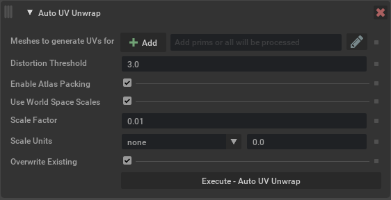
Auto UV Unwrap#
This operation generates texture(UV) coordinates for mesh prims with lower distortion than projection based methods, and adds them as the st primvar.
Argument |
Description |
|---|---|
Meshes |
Determines which meshes to generate UVs for. Meshes can be selected in USD Composer and added here using the Add button, or names can be typed in directly. Path expressions can be used. |
Distortion Threshold |
Distortion threshold for the AutoUV algorithm (should be greater than 1). Lower values result in unwraps with lower distortion but more islands, while higher values result in fewer islands but higher distortion. |
Enable Atlas Packing |
Generates tightly packed, non-overlapping UV islands if enabled. Otherwise, UV islands will overlap (ok for tiling textures). |
Use World Space Scales |
Scales UV islands to world space dimensions of the source mesh. Otherwise, scales UV coordinates to [0, 1]^2 range. |
Scale Factor |
Apply a different scale factor to the generated UVs, higher numbers will increase texel density(more repeating tiling) and lower numbers have less density(less repeating tiling). |
Scale Units |
Use predefined real world scale units that will set the scale factor to the corresponding value. |
Overwrite Existing |
Overwrite existing UVs on defined meshes if enabled (default setting), when disabled this will only create UVs for meshes that don’t have any existing UV primvars. |
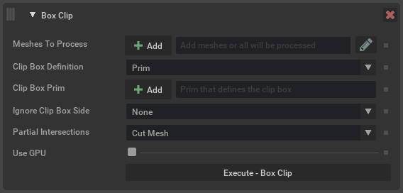
Box Clip#
This operation clips mesh prims to the provided world-space axis-aligned bounding-box.
Argument |
Description |
|---|---|
Meshes to process |
Define the prim paths to operate on. Meshes can be selected in USD Composer and added here using the Add button, or names can be typed in directly. Path expressions can be used. Note If left blank, all meshes in the scene will be clipped. Tip When adding a top level parent like a xform, use the path expression |
Clip Box Definition |
Sets how the world-space clip box is defined.
|
Clip Box Prim |
Define a prim to use as the clipping area. Note This will use the input prim’s bounding box, not the defined geometry. |
Ignore Clip Box Side |
Allows ignoring a side of the clip box (extending it to infinity in that direction).
|
Partial Intersections |
Defines how meshes that partially intersect the clip box are handled.
|
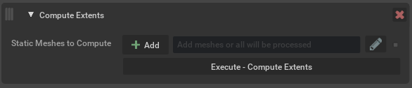
Compute Extents#
This will compute/recompute and author the extents property for meshes. If the meshPrimPaths option is empty, all prims in the stage will be computed.
Extents are the axis aligned bounding boxes of the meshes, these do not always exist in a USD file. The extents can be used to improve scene performance since they allow the application to know the exact bounds of an object. Running this operation on an imported stage can potentially help improve overall render and stage traversal performance.
Argument |
Description |
|---|---|
Static Meshes To Compute |
Defines the meshes to operate on. Note If left blank, all meshes in the scene will be considered (default setting). |
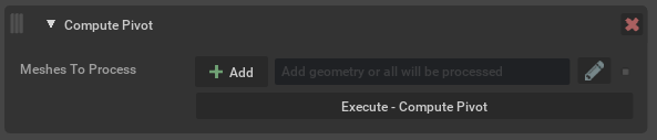
Compute Pivot#
Compute Pivot will place the parent transform at the center of the bounding box of the target mesh, think of this as creating a center pivot in other DCC tools. This makes it easier to interact with objects in the scene because the transform manipulator is centered on the object.
Some tools generate scenes where the transform is at the origin, meaning it is far from the actual vertices, making it hard to move a mesh precisely.
Argument |
Description |
|---|---|
Prims To Process |
Defines the prims to operate on. Prims can be selected in USD Composer and added here using the Add button, or names can be typed in directly. Path expressions can be used. Note If left blank, all prims in the scene will have their pivot computed. |
Overwrite Authored Pivots |
By default this operation will not overwrite any existing pivot. If this option is checked then existing ones will be replaced. |
Apply To |
Where to apply pivots - either to only Meshes, or Meshes and Xforms. |
Method |
The default |
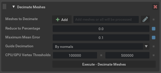
Decimate Meshes#
Reduce decimation amount on an input UsdGeom mesh primitive type.
Argument |
Description |
|---|---|
Meshes to Decimate |
Defines the prims to operate on. Prims can be selected in USD Composer and added here using the Add button, or names can be typed in directly. Path expressions can be used. Note If left blank, all mesh prims in the scene will be considered (default setting). |
Reduce to Percentage |
The amount percentage to reduce targeted mesh prims. Depending on the input amount, the operation will try to reduce meshes to the defined target reduction percentage. For example, if the value is Note Acceptable input values are 0.0-100.0 |
Maximum Mean Error |
The mean error amount that is acceptable distance for the decimation reduction factor. Lower numbers have a closer trace tolerance to retain more model information(recommended), higher values will yield lower face counts. Caution If both Reduction Factor and Maximum Mean Error are set, the decimator stops when it reaches the Reduction Factor target or can’t find any moves within the error bounds, whichever happens first. If both values are set to 0, the decimation will automatically reduce to the smallest possible face count for the inputs. If guide attributes are supplied, they can contribute to the measured error. The amount of simplification obtained at the same max-mean-error tolerance can be less if there is a guiding attribute. Note Acceptable values for max mean error are any positive value. |
Guide Decimation |
Guide the decimation by using normals or colors (if available). Makes the operation pay closer attention to the provided attribute. By default, the operation will use normals (if available) as the guiding attribute. Note If there are no existing normals on input mesh prims, this will affect the output mesh display. It is recommended that normals be created in DCC/authoring package prior. |
Pin mesh boundaries |
Preserve mesh boundaries when performing decimation. |
Topology Simplification |
Allows the decimator to perform topological changes—cutting through handles, closing holes, or merging openings—when the geometric error is acceptable. By default, the decimator preserves the original topology of your mesh, maintaining all handles, tunnels, and holes. While this ensures structural integrity, it can limit simplification on complex surfaces with intricate topological details, such as speaker grilles or mesh patterns. Enable this option when working with highly detailed meshes where preserving every topological feature isn’t critical and want maximum polygon reduction. |
CPU/GPU Vertex Thresholds |
Controls what internal algorithm the operation will use for a given mesh prim. When the vertex count of a mesh is higher than the first value, a CPU parallel algorithm is used, and when higher than the second value a GPU algorithm is used. |
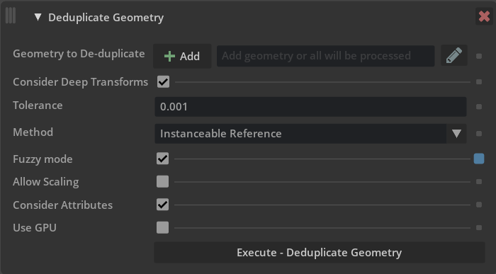
De-duplicate Geometry#
This will replace multiple duplicate geometric prims in a scene to a single prim and create references/instances to the single prim. Since a referenced prim uses less memory than the full duplicated prim, this option can reduce system memory and vram consumption.
This process is only effective if there are prims that are identical but are not already instanced; however, you may find this optimization may not have any effect on your scene. To see what optimizations will take place, we will want to utilize Window -> Utilities -> Statistics window to see before and after the optimization metrics.
The operation also supports a fuzzy comparison mode. In this mode, the similarity measure used is independent of the tessellation of meshes and based on their relative shape deviation. The fuzzy mode comparison is available as a CPU and GPU implementation.
This process supports deduplicating point-based geometry (meshes, basis curves, etc.). Note that in fuzzy mode, currently only meshes are supported for deduplication.
Argument |
Description |
|---|---|
Geometry to De-duplicate |
Defines the geometry to operate on. Prims can be selected in USD Composer and added here using the Add button, or names can be typed in directly. Path expressions can be used. Note If left blank, all meshes in the scene will have their pivot computed (default setting). |
Tolerance |
Acceptable point position change during deduplication. The value is a stage unit and before and after point positions are compared in world space. For fuzzy deduplication the tolerance value represents a maximal relative deviation of the oriented bounding box extents and volumes of two meshes to be considered equal. Caution The meaning of this argument changed in version 105.0.6, values of |
Method |
Determines which operation to use when processing inputs. The options are:
Caution Multiple De-duplicate Geometry processes run in succession can lead to unreliable results and possible kit instability. It is recommended to run this process with the default settings to achieve the best results. |
Ignore Attributes |
When using the Reference or Instanceable Reference methods prims are required to have matching attributes
and attribute values in order to be considered for deduplication. For example, two prims with a different
This argument allows you to specify either attribute names or an entire namespace (enabled if the value ends with
a |
Fuzzy Mode |
Determines the mode of comparison. When enabled, the similarity measure used is independent of the tessellation of meshes and based on their relative shape deviation. |
Allow Scaling |
Available when fuzzy mode is enabled, the comparison factors out uniform scaling. |
Use GPU |
Available when fuzzy mode is enabled, the comparison will be performed on GPU. Note GPU mode is only available for fuzzy mode. |
Consider Deep Transforms |
When enabled (default), this will look for duplicate prims where point values have been uniformly transformed. Note Consider Deep Transforms is not available for fuzzy mode. |
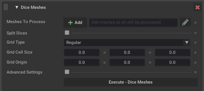
Dice Meshes#
This operation will create new vertices and faces where needed based on regular or irregular input grid parameters. Each grid cell should be self-contained, as in there should be no part of the sub-mesh that extends outside the grid cell definition.
Caution
To create separate mesh prims after the dice meshes has completed, use the Split Meshes operation or enable Split Dices to split desired geometry.
Argument |
Description |
|---|---|
Meshes to Process |
Defines the prims to operate on. Prims can be selected in USD Composer and added here using the Add button, or names can be typed in directly. Path expressions can be used. Note If left blank, all mesh prims in the scene will be considered (default setting). |
Split Dices |
If enabled, resulting diced meshes will be split into separate prims. |
Grid Type |
The type of grid to use for the dicing.
|
Advanced Settings |
If enabled, allows setting custom up vectors for the grid.
|
Edit Stage Metrics#
This operation changes the metersPerUnit and/or upAxis of a stage’s active edit target layer by updating the layer’s metadata and applying relevant transformations to attributes that represent world space units so that they reflect the new metersPerUnit/upAxis.
Note
Edit Stage Metrics operation is designed to only modify attributes that represent a world space value in the stage’s active edit layer. This means prims/attributes that exist in the scene from external references or sublayers will not be affected by the operation. See Encoding Stage UpAxis
An overview of some specifics about how the operation will affect attributes or xformOps in the stage:
When changing the
metersPerUnitof prims that are a defined schema that have inferred attributes values that don’t need to be defined. For example a Cube prim has asizeattribute that does not need to be defined, and if it is not the cube will have a value of2.0.When changing the
metersPerUnit, the operation needs to create thissizeattribute in order to scale its inferred value of2.0. These inferred attributes will only be created if they represent world space values and the prim of the attribute exists as a concretedefin the active edit layer.When changing the
upAxisof transforms that contain rotations it is not a straight forward problem due to rotation order needing to change in some instances, the Edit Stage Metrics operation will currently collapse a prim’sxformOpstack into a single matrixxformOp.This creates a few cases with surprising behavior, for example if the edit stage layer contains an
overon a singlexformOpin a stack ofxformOpson a prim in the underlying sublayer/reference, this will cause the entirexformOpstack to have its up axis transformed even though only a part of the stack exists in the active edit layer.

Argument |
Description |
|---|---|
Meters Per Unit |
Set the meters per unit value to one of the following value:
|
Up Axis |
Set the up axis for the stage to one of the following:
Caution X up axis is not supported. |
Collapse Xforms |
When enabled the xformOps stack will be collapsed into a single matrix when changing up axis. |
Ignore Kit Cameras |
Ignore the Kit built-in viewport cameras (such as persp, front, top, right) when changing stage metrics. Note The viewport in UI mode applies correction transforms to viewport cameras. Scene Optimizer CLI mode is not affected by the viewport extension and cameras will work as intended. |
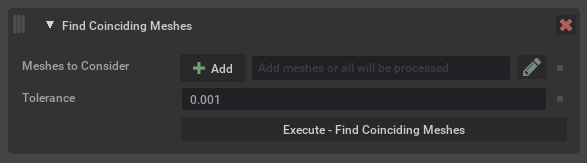
Find Coincident Geometry#
Find any geometry type prim that occupies the same positional space in a scene.
Argument |
Description |
|---|---|
Meshes to Consider |
Defines the geometry prims to consider when looking for coinciding geometry. |
Tolerance |
Tolerance value when comparing points in world space. Tolerance is the max distance between points in world space using stage units. |
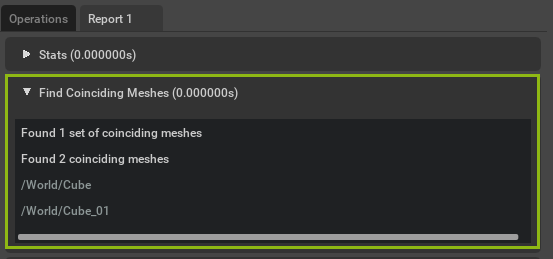
Results will be displayed in the generated report tab and affected prim paths can be copied by right clicking on them in the report.#
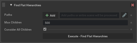
Find Flat Hierarchies#
Finds prims that have more than a specified number of children.
Argument |
Description |
|---|---|
Paths |
Defines the prim paths to consider when looking for flat hierarchies. |
Max Children |
The maximum number of children a prim can have until it is considered a flat hierarchy. |
Consider All Children |
Specifies whether to consider all children or only active, loaded, defined, non-abstract children. |
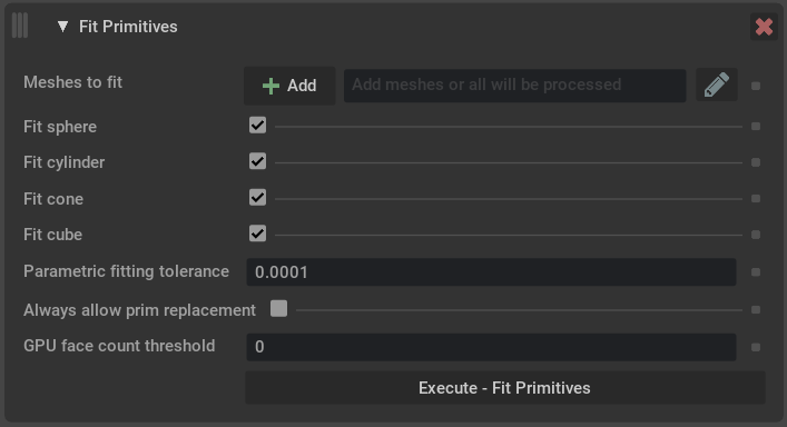
Fit Primitives#
This operation attempts to fit transformed primitive shape prims (sphere, cylinder, cone, or cube) to selected meshes. If the mesh can be fit within tolerance, it is replaced with the transformed primitive that fits best. The user can choose which of the four primitive types (in any combination) to attempt to fit.
Argument |
Description |
|---|---|
Meshes to fit |
Define the prim paths to operate on. Meshes can be selected in USD Composer and added here using the Add button, or names can be typed in directly. Path expressions can be used. Note If left blank, primitives will be fit to all meshes in the scene. Tip When adding a top level parent like a xform, use the path expression |
GPU face count threshold |
Minimum number of faces needed to trigger the GPU algorithm. If 0 is input, then GPU is not selected. |
Vertex error tolerance |
Threshold required to allow primitive replacement. This is a relative tolerance based input mesh components. For spheres, cylinders, and cubes the tolerance represents the allowed distance of vertices from the fitting surface relative to the size of the mesh. For cones, the tolerance distance is proportional to the distance away from the cone’s apex. |
Volume fill tolerance |
The difference between the volume of the fit primitive and the original mesh must be within this relative tolerance. |
Ignore non-const primvars |
If checked, meshes with non-constant primvars are considered for primitive fititng. If replaced by a primitive, then any a non-constant primvars are removed. |
Ignore subsets |
If checked, meshes with subsets are considered for primitive fitting. If replaced by a primitive, then any subsets are removed. |
Allow negative volume |
If checked, then a mesh with negative volume (inward-pointing normals) is allowed to be fit. |
Allow missing endcaps |
If checked, then a cylinder, cone, or box mesh without endcaps is allowed to be fit. |
Fit sphere |
If checked, attempt to fit a transformed sphere to the selected meshes. |
Fit cylinder |
If checked, attempt to fit a transformed cylinder the selected meshes. |
Fit cone |
If checked, attempt to fit a transformed cone to the selected meshes. |
Fit cube |
If checked, attempt to fit a transformed cube to the selected meshes. |
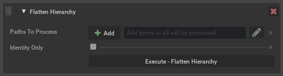
Flatten Hierarchy#
Finds any Xforms in a stage that are redundant and removes them, in order to reduce prim count. This is typically an Xform that has a single Xform underneath it, or chains of single Xforms.
Certain conditions prevent an Xform from being removed. This includes Xforms that have multiple children, in order to retain some semblance of scene layout. Also Xforms that have a relationship (for example a material binding) or something that has a relationship targeting them (e.g. a material). Xforms that have time samples are not removed. Only Xforms in the current edit target are considered, any external references will be skipped.
Xforms that are referenced (for example as an instance) must also retain their original path, however Xforms underneath them can potentially be removed.
Argument |
Description |
|---|---|
Paths To Process |
The prim paths to process. Any paths will be recursively processed to find redundant Xforms descending from them. Prims can be selected in USD Composer and added here using the Add button, or names can be typed in directly. Path expressions can be used. Note If left blank, the whole scene will be processed. |
Identity Only |
By default any unnecessary Xform can be removed, even if it contributes an opinion about transformation. The values it contributes will be added to a parent Xform to ensure prims retain their correct world position. If this option is enabled then only Xforms that do not contribute an opinion will be removed. That is, they have an identity transform or have no opinion on transform at all. |
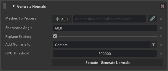
Generate Normals#
Generates new normals for the given UsdGeomMeshes.
Argument |
Description |
|---|---|
Meshes To Process |
Defines the prims to operate on. Prims can be selected in USD Composer and added here using the Add button, or names can be typed in directly. Path expressions can be used. Note If left blank, all mesh prims in the scene will be considered (default setting). |
Sharpness Angle |
The absolute value of the dihedral angle at an edge above which the edge is considered sharp.
The dihedral angle is measured in the range Note Applies only when generating Corner normals. |
Replace Existing |
When enabled, any existing normals on the mesh will be replaced. Otherwise, normals are only generated for meshes that had none. |
Add Normals to |
Determines what type of normals to generate, per |
Weighting |
Weight each contribution to the final normal by Note Applies only when generating Vertex normals. |
GPU Threshold |
If the number of normals to generate exceeds this threshold, then use a GPU algorithm. |
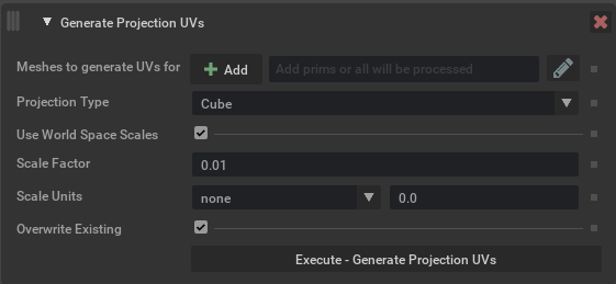
Generate Projection UVs#
This operation generates texture(UV) coordinates for mesh prims, using the chosen projection type, and adds them as the st primvar.
Argument |
Description |
|---|---|
Meshes |
Determines which meshes to generate UVs for. Meshes can be selected in USD Composer and added here using the Add button, or names can be typed in directly. Path expressions can be used. Note If left blank, all meshes in the scene will be considered (default setting). |
Projection Type |
Determines what type of projection is to be used. The options are:
|
Use World Space Scales |
Determines whether to scale the source geometry to its world space dimensions before projection. |
Scale Factor |
Apply a different scale factor to the generated UVs, higher numbers will increase texel density(more repeating tiling) and lower numbers have less density(less repeating tiling). Note
|
Scale Units |
Use predefined real world scale units that will set the scale factor to the corresponding value. |
Overwrite Existing |
Overwrite existing UVs on defined meshes if enabled (default setting), when disabled this will only create UVs for meshes that don’t have any existing UV primvars. |
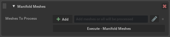
Manifold Meshes#
This operation makes the input UsdGeom mesh primitives to be manifold.
Argument |
Description |
|---|---|
Meshes to process |
Defines the prims to operate on. Prims can be selected in USD Composer and added here using the Add button, or names can be typed in directly, path expressions can be used. Note If left blank, all mesh prims in the scene will be considered (default setting). |
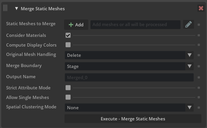
Merge Static Meshes#
The merge static meshes process replaces multiple meshes that share common properties with a single merged mesh. This reduces scene prim count and can improve overall stage performance.
Caution
Once merged, you can no longer edit individual original meshes, but only the new merged mesh prims.
Argument |
Description |
|---|---|
Static Meshes To Merge |
Defines the meshes to operate on. Meshes can be selected in USD Composer and added here using the Add button, or names can be typed in directly. Path expressions can be used. By default, Merge Static Meshes will skip any invisible prims. However if you specify an explicit path to an invisible prim here then that prim and any of its children will also be considered for merging. This is to allow supporting “Geometry Libraries”, where a scene may be structured with a number of invisible meshes that are referenced elsewhere in the scene. Note If left blank, all meshes in the scene will be considered (default setting). |
Keep Materials Separate |
Defines how meshes with different materials are handled. If this option is selected, meshes with the same material will be merged. If not selected, all meshes will be merged regardless of original material. Materials will be preserved on the output mesh and assigned to individual faces using geomSubsets. |
Compute Display Colors |
Set display color and opacity to values computed from the bound material. The assign display color option will look at the following USD prim attributes on either the material or the surface shader currently assigned to the source mesh prim or prims:
Opacity will be derived from This option is disabled by default. Note We currently don’t support deriving any of this information from texture inputs that are connected to bound materials. And if no value is present we will set the value of the color to |
Original Mesh Handling |
What to do with any meshes in the original scene that were merged. They can be ignored, deleted, deactivated or hidden. |
Merge Boundary |
Defines where the merged geometry should be parented. The options are:
Click these links for more information on USD Kinds: |
Output Name |
The name prefix to use for newly created merged meshes. Can also be a partial path, eg |
Strict Attribute Mode |
Makes the merge process more conservative, requiring every attribute on a prim to match, rather than a smaller list of attributes that are known to prevent merging. This is intended to be useful in the case that meshes should not be merged together due to attributes that aren’t understood by Merge. |
Allow Single Meshes |
When enabled, means that a single mesh will still be “merged”. While there is nothing for it to merge with it means it will be processed and potentially moved to the same location as other merged meshes. |
Spatial Clustering Mode |
Whether or not to spatially cluster meshes. There are currently two modes available:
Note Spatial Clustering only happens within Merge Boundaries. |
Spatial Threshold |
The distance between which two meshes can be considered close enough. |
Spatial Max Size |
The maximum size of an output mesh when clustering meshes spatially. |
Spatial Vertex Count |
The maximum number of vertices that we can cluster together. |
Merge Results (Report)#
Note
A report will be generated by default when any Scene Optimizer operation is executed from core version 105.1.8 and newer. The report can be turned off in the Configure Menu by disabling Generate Report option.
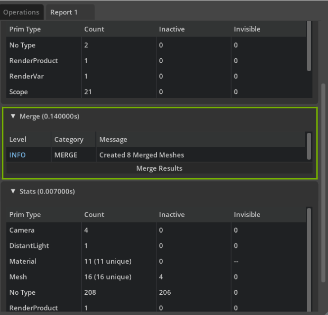
In the merge stats results there is the option to view the Merge Results which will give a detailed view of how prims were merged.#
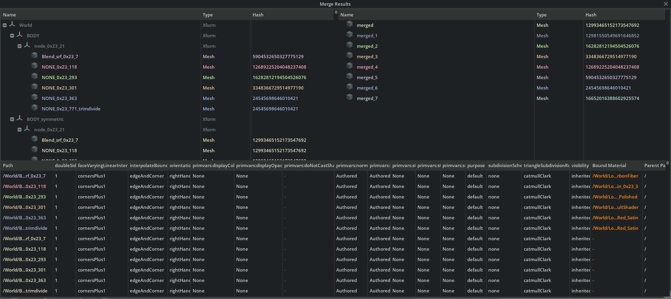
Merge Results with attribute information about prims to be merged and resulting merged output details.#
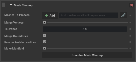
Mesh Cleanup#
Applies the selected cleanup operations on meshes; for example, merging vertices in the input that are within a given tolerance.
Argument |
Description |
|---|---|
Meshes to process |
Defines the prims to operate on. Prims can be selected in USD Composer and added here using the Add button, or names can be typed in directly. Path expressions can be used. Note If left blank, all mesh prims in the scene will be considered (default setting). |
Merge Vertices |
If enabled, merge vertices that are deemed coincident, based on the tolerance grid. Two vertices are collocated if they have exactly the same coordinates, optionally, after dropping a certain number of precision bits or snapping (rounding) coordinates to the tolerance grid. The following options apply only when merging vertices:
|
Contract degenerate edges |
If enabled, merge consecutive repeated vertex references around a mesh face. Note Degenerate edges are determined solely by having the same vertex index at both ends. In other words, the positions of vertices plays are not taken into consideration. |
Remove degenerate faces |
If enabled, remove faces with fewer than 3 distinct vertex references. |
Remove isolated vertices |
If enabled, remove isolated (unreferenced) vertices. |
Remove duplicate (lamina) faces |
If enabled, remove duplicate (lamina) faces on a mesh. |
Make Manifold |
If enabled, ensure the output is a manifold mesh. |
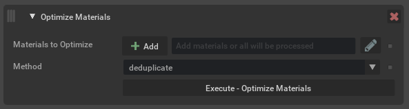
Optimize Materials#
Run operations to optimize materials in a stage. Run this optimization to replace duplicates with references to unique materials. This can reduce memory usage and also improve performance.
Argument |
Description |
|---|---|
Materials to Optimize |
Determines which materials to modify, are able to target subsets. Materials can be selected in USD Composer and added here using the + option, or names can be typed in directly. Path expressions can be used. Note If left blank, all materials in the scene will be considered (default setting). |
Method |
Determines which operation to use when processing inputs.
|
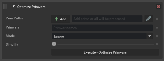
Optimize Primvars#
Run operations to optimize primvars in the stage. This tool can convert flat primvars to indexed, or indexed primvars to flattened. It can also
attempt to simplify primvars. For example if a primvar is authored as faceVarying (a value per vertex), but all the values are equal, this
can be simplified to constant interpolation. Or if all the values for each face are equal, it could be reduced to uniform interpolation.
Flattening refers to removing indexing from a primvar and authoring all of the values in one array, whether they are unique or not. This may take more disk space. Indexing refers to recording only unique values in the primvar data, and having separate indices that refer to the unique values. This can take less space, particularly if there are not many unique values versus the length of the array.
Argument |
Description |
|---|---|
Prim Paths |
Determines which prims to process primvars for. Prims can be selected in USD Composer and added here using the + option, or names can be typed in directly. Path expressions can be used. Note If left blank, all prims in the scene will be considered (default setting). |
Primvars |
An optional comma-separated list of primvar names (without the If left blank then all primvars will be operated on. If specified, then only the named primvars will be considered. |
Mode |
Determines what to do with primvars.
|
Simplify |
Determines whether or not to try and simplify any primvars that are encountered. Note When using the Authoring Mode |
Remove If Bound |
This option relates to using the mode You can use this, for example, to remove |
Optimize Skeleton Roots#
This operation will merge all meshes for meshes attached to a skeleton. This can greatly improve character playback speed by optimizing scenes for GPU skinning computation.
This is a good option to try if you have rigged characters that use UsdGeomSkel. It will merge all meshes on the skeleton into a single mesh. Similar to merge static meshes, this will not significantly reduce memory usage.

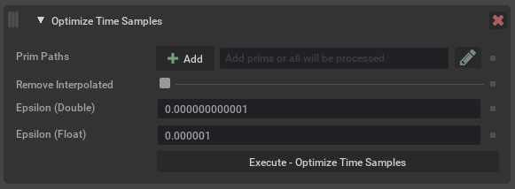
Optimize Time Samples#
This operation checks for redundant time-samples on attributes and removes them.
Argument |
Description |
|---|---|
Prim Paths |
Defines the prims to check. Prims can be selected in USD Composer and added here using the Add button, or names can be typed in directly. Path expressions can be used. Note If left blank, all prims in the scene will be considered (default setting). |
Remove Interpolated |
If enabled this means any time-samples that are different but can be linearly interpolated will also be removed. After using this option, playing back a stage set to This option only applies to floating-point types for which USD supports interpolating timesamples. Click here to view OpenUSD’s API docs on linear interpolation. |
Epsilon (Double) |
The epsilon to use when considering whether two double values should be treated as equal even though they are different by some small amount, to account for floating-point precision differences. |
Epsilon (Float) |
The same as Epsilon (Double) but for float types. Typically this is smaller due to floating-point precision issues with floats vs doubles. |
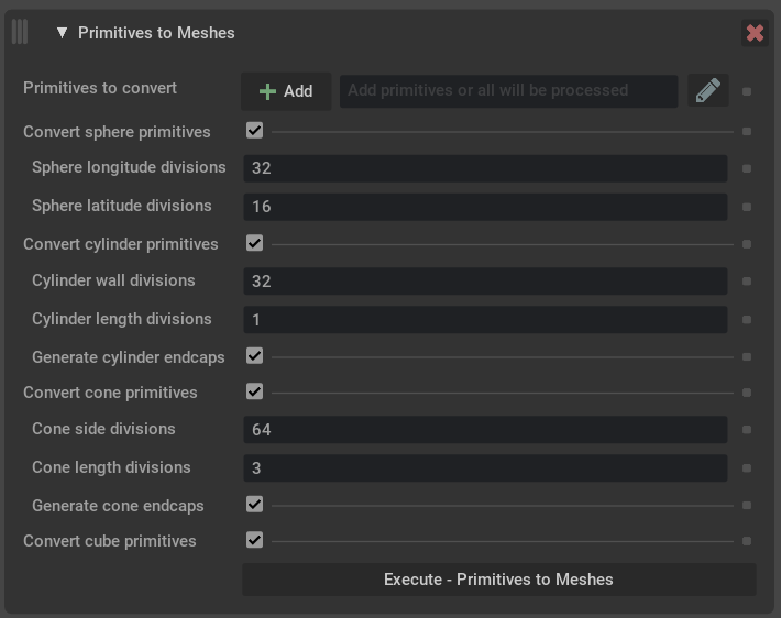
Primitives to Meshes#
This operation replaces gprim types sphere, cylinder, cone, and cube with a mesh approximation. This allows the geometry to be used with operations that require mesh types.
Argument |
Description |
|---|---|
Primitives to convert |
Define the prim paths to operate on. Prims can be selected in USD Composer and added here using the Add button, or names can be typed in directly. Path expressions can be used. Note If left blank, primitives will be fit to all meshes in the scene. Tip When adding a top level parent like a xform, use the path expression |
Convert sphere primitives |
Whether or not to convert spheres. |
Sphere longitude divisions |
The number of divisions around the equator in the sphere’s tessellation. |
Sphere latitude divisions |
The number of pole-to-pole divisions in the sphere’s tessellation. |
Convert cylinder primitives |
Whether or not to convert cylinders. |
Cylinder wall divisions |
The number of divisions around the cylinder wall in its tessellation. |
Cylinder length divisions |
The number of end-to-end divisions in the cylinder’s tessellation. |
Generate cylinder endcaps |
Whether or not to add endcaps to cylinder meshes. |
Convert cone primitives |
Whether or not to convert cones. |
Cone side divisions |
The number of divisions around the side of the cone in its tessellation. |
Cone length divisions |
The number of divisions along the length of the cone int its tessellation. |
Generate cone bases |
Whether or not to add a base to cone meshes. |
Convert cube primitives |
Whether or not to convert cubes. |
Organize Prototypes#
Reparent internal scene-graph instance prototypes under a user-specified namespace.

Argument |
Description |
|---|---|
Prototypes Namespace |
Namespace (default setting “Prototypes”) where prototypes will be reparented. |
Preserve Hierarchy Levels |
The number of the prototype’s immediate ancestors to retain when reparenting. For example, original prototype |
Prune Leaves#
This operation finds and prunes any leaf grouping primitives found in a stage (for example Xform, Scope).

Argument |
Description |
|---|---|
Prim Paths to Search |
Search for empty grouping primitives on these paths (inclusive). Path expressions can be used. Note No grouping primitives above the specified paths will be considered for pruning, even if they end up being empty as a result of this operation. Note If left blank, all paths in the stage will be considered (default setting). |
Method |
Delete or deactivate any leaf prims that are found. |
Filter Inactive Prims |
Ignore inactive prims (i.e. do not consider them empty leaves). |
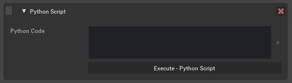
Python Script#
This operation executes user defined python code with access to the current stage. It can be used to manipulate the stage in ways not currently supported by the Scene Optimizer. The python script can be stored in the Preset configuration file, making it reusable and portable.
Argument |
Description |
|---|---|
Python Script |
The python code to run when executing this operation. The following variables will automatically be available during execution:
Note This is a python only feature and cannot be used from the Standalone application. Caution This operation is not available for custom code execution in USD Explorer. |
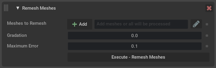
Remesh Meshes#
This operation will remesh input mesh prims to a defined tolerance to create a new mesh topology. Input mesh and normals will guide the maximum error and size of the triangles to match input volume.
Caution
Stage units will affect scale of input values.
Argument |
Description |
|---|---|
Meshes to Remesh |
Meshes can be selected in USD Composer and added here using the Add button, or names can be typed in directly. Path expressions can be used. Note If left blank, all meshes in the scene will be considered (default setting). |
Gradation |
Controls the rate of growth of triangles sizes, when low surface curvature allows it without exceeding the permitted error amount. A gradation of 0 indicates that there can be no growth, and therefore forces all edges to be of (nearly) the same length, as controlled by the Maximum Error parameter. If a mesh consists of precisely equilateral triangles only, then all the edges in the mesh (at least within a connected component) would have to be of exactly the same length, and every triangle would have the same area. Therefore, the smaller this common edge length, the larger the number of triangles needed to cover the input surface area. This uniform coverage can be a very inefficient representation for low-curvature or flat regions of surface where much larger (and fewer) triangles would be sufficient to reach a desired level of precision. By allowing the triangles to deviate a little from being perfectly equilateral, the edge lengths can grow gradually from some part of the surface to another. The gradation parameter indirectly controls the permitted amount of deviation from equilaterality. The larger the gradation, the faster the pace of edge-length growth, but also the higher the observable deviation of output triangles from equilaterality. |
Maximum Error |
The approximate distance allowed between the original surface and the remeshed one. This parameter also sets the shortest permitted edge length (up to a tolerance factor) to the maximum error times square root of 3. So, for example, a maximum error of 0.1 would produce a mesh where the shortest edge length (or indeed all edges lengths if the gradation is 0) would be around 0.173. Note Input units scale are matched to the current stage units, this is an approximate local measuring based on some smooth interpretation of the input mesh. |
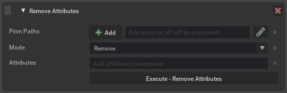
Remove Attributes#
This operation will find and remove attributes from prims. Exact attribute names can be specified, or namespaces can be used to remove any attribute with a matching namespace prefix.
When using the Remove mode, attributes can only be removed from the current edit target. This means that if the edit target has an opinion on an attribute, and there is also a weaker opinion (for example, overriding an attribute on a prim that has been referenced), then the original referenced value will now be in use. If there was no stronger opinion in the current edit target (for example, a prim was referenced and does not override the attribute), then nothing happens, as the edit target contains no opinion to remove.
Blocking an attribute means the attribute remains authored but has no value. This becomes the strongest opinion meaning regardless of the prims composition the attribute has no effective value.
Argument |
Description |
|---|---|
Prim Paths |
Determines which prims to process. If left blank, all prims are checked. |
Mode |
The action to apply to matching attributes.
|
Attributes |
A list of attributes or namespaces to remove or block. Anything ending with a |
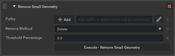
Remove Small Geometry#
This operation will find and remove small or degenerate geometry in the scene. Degenerate geometry are prims with an extent size of 0.0, whereas small geometry is defined by a percentage size of the overall scene’s median extent size.
Argument |
Description |
|---|---|
Paths |
Determines which prims to consider for removal. Note The entire stage is still processed in order to find the median extent size. |
Remove Method |
The method used to remove small geometry.
|
Detection Method |
Method that will be used for detecting small geometry.
|
Threshold |
Threshold that represents the size at which extents are considered small (how this is compared depends on the detection method). Note Regardless of the detection method, a threshold of 0.0 will mean only degenerate geometry is removed. |
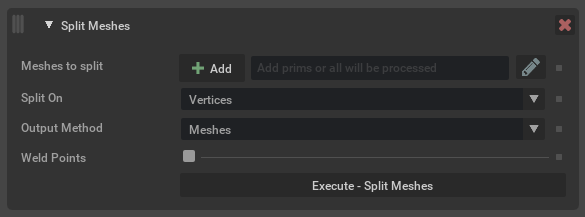
Split Meshes#
This operation determines whether meshes in a stage contain multiple disjoint mesh descriptions, specifically parts of a mesh that don’t share any vertices. These can then be replaced with multiple mesh prims that contains their defined entity part of the geometry.
When the Spatial Clustering Mode is enabled meshes will be split and merged spatially by user specified values. This also greatly improves processing performance when running in this mode to split and merge meshes in a single process verses running each operation separately.
Argument |
Description |
|---|---|
Meshes to split |
Determines which meshes to operate on. Meshes can be selected in USD Composer and added here using the Add button, or names can be typed in directly. Path expressions can be used. Note If left blank, all meshes in the scene will be considered (default setting). |
Split On |
Determines how to attempt splitting meshes. The options are:
|
Split Collocated Points |
If enabled, points that are collocated will be considered when splitting a disjoint mesh. Note This does not modify the output topology; duplicates will still exist. It is only for the purpose of determining what is disjoint. |
Original Mesh Handling |
What to do with any meshes in the original scene that were split or merged. They can be ignored, deleted, deactivated or hidden. |
Spatial Clustering Mode |
Mode that allows splitting and merging of meshes in a single process based on a spatial size. When changed from
Caution These bounding box spatial values are based on the current stage defined meters per unit (MPU). Values that are too small may create unexpected results or no merging of split meshes.
|
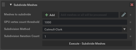
Subdivide Meshes#
This operation performs either Catmull-Clark or Loop subdivision on meshes in a stage, replacing the topology with the subdivided result. Mesh subsets are forwarded and floating-point data defined on corners and vertices will be interpolated.
Creases and corners may be described using the crease and corner index attributes of UsdGeomMesh. See creaseIndices, creaseLengths, creaseSharpnesses, cornerIndices, and cornerSharpnesses. The resulting mesh will have updated crease and corner attributes, reflecting edge and vertex forwarding from the original mesh to the result. Also, the forwarded sharpnesses will be decremented by 1 with each subdivision iteration. Non-positive sharpnesses result in the removal of creases or corners. This way the operation may be repeatedly applied to a mesh, leading to consistent sharpnesses of crease and corners regardless of how many iterations are performed with each execution of the operation.
Note
No normal recalculation to account for curvature introduced by the subdivision algorithm is applied to resulting output mesh.
Argument |
Description |
|---|---|
Meshes to subdivide |
Define the prim paths to operate on. Meshes can be selected in USD Composer and added here using the Add button, or names can be typed in directly. Path expressions can be used. Note If left blank, all meshes in the scene will be subdivided. Tip When adding a top level parent like a xform, use the path expression |
GPU face count threshold |
Minimum number of faces needed to trigger the GPU algorithm. |
Maximum face count |
Maximum number of faces the final subdivided result can have, if there are more than the limit subdivision will not be performed. |
Subdivision Method |
Which algorithm to use.
|
Subdivision Iteration Count |
How many subdivision iterations to apply to each mesh.
|
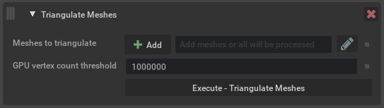
Triangulate Meshes#
Takes polygonal meshes and rewrites them to use only triangles.
Argument |
Description |
|---|---|
Meshes to triangulate |
Define the prim paths to operate on.
Note If left blank, all meshes in the scene will be triangulated. |
GPU vertex count threshold |
If a mesh has more vertices than this threshold, then use a GPU algorithm. |
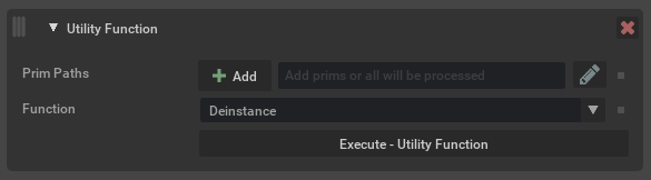
Utility Functions#
This operation contains a number of smaller functions that don’t necessarily need a full operation of their own. Generally this would mean they are a simple process that does not require any real configuration.
Argument |
Description |
|---|---|
Prim Paths |
Defines the prims to operate on. Prims can be selected in USD Composer and added here using the Add button, or names can be typed in directly. Path expressions can be used. Note If left blank, all prims in the scene will be considered (default setting). |
Function |
The utility function to run. The current available functions are:
|