Physics Authoring Toolbar (PhysX Support UI)#
Overview#
This extension provides a toolbar including tools to streamline Physics authoring User Experience.
The goal is to make physics authoring more accessible and as much automated as possible.
Using the Omniverse Physics Authoring Toolbar begins with enabling the extension.
Check if extension is enabled#
You can see if the extension is loaded by checking if the Physics Authoring Toolbar menu item exists.
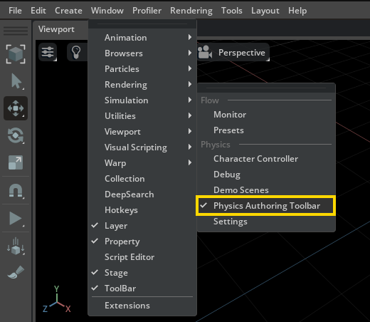
If the Physics Authoring Toolbar menu item is missing, then it means that the extension is disabled.
Note
Omniverse USD Composer has the Support UI Extension enabled by default.
Enable the extension#
To enable the extension:
Navigate to
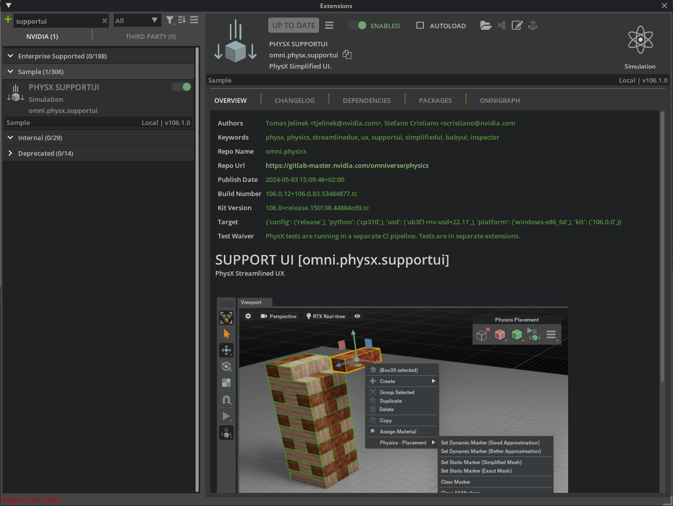
window > extensionsIn the search bar enter
Support UILocate the Support UI extension and select it.
Select the
Enabledtoggle to enable the extension.Select the
Check Marknext to auto-load to Load the Extension Automatically on App Start if desired.Close the Extensions Panel.
At this point the extension should be enabled.
Click Window -> Simulation -> Physics Authoring Toolbar menu item and you should now see the support ui toolbar docked on the right of the viewport.
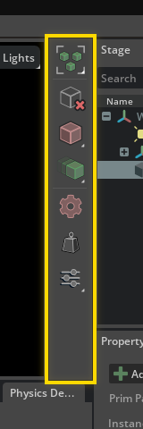
Physics Authoring Toolbar#
Authoring toolbar lets you create static and dynamic colliders (together with rigid bodies), enable automated creation of colliders, remove all physics components on prims, enable rigid body manipulator and selection mode and more.
Action |
Description |
|---|---|
Rigid Body Selection Mode |
Toggles selection mode, which always tries to select an asset that contains a rigid body component. |
Remove Physics Components |
Removes all physics components on selected assets. |
Create Static Colliders |
Creates static collider types on selected assets. |
Create Dynamic Colliders |
Creates dynamic collider types on selected assets. |
Automatic Creation of Colliders |
Toggles automated creation of colliders. |
Mass Distribution Manipulator |
Toggles the Mass Distribution Manipulator. |
Settings |
Configures additional options, including the Physics Inspector |
Rigid Body Selection Mode#
Rigid Body Selection Mode is a special selection mode, which always tries to select an asset that contains a rigid body component. If current selection does not have it, it scans parent hierarchy starting from the current selection. If there is no rigid body found, current selection is preserved.
Rigid Body Manipulator#
The extension brings a custom version of gizmo manipulator called Rigid Body Manipulator, tailored specifically for physics-ready assets.
Note
Rigid Body Manipulator is by default enabled but works only in Simulation Mode and with only with physics-ready assets which have a rigid body component in hierarchy!
When active, the transform gizmo in simulation mode is moving and rotating objects using physics force, therefore objects properly collide with each other, links are used etc.
Note
Scaling is not supported.
Remove Physics Components#
Removes all physics components on selected assets. E.g., all colliders, rigid bodies, mass settings, etc.
Create Static Colliders#
Creates non-moveable colliders on all selected geometric assets and on their geometric children.
Note
While set to Static, objects cannot be moved with the transform gizmo.
Collider type can be selected via this button’s drop-down menu (hold left mouse button for a bit to open it).
- Supported types:
Triangle Mesh = Exact Mesh, no approximation
Mesh Simplification Approximation = Simplified Mesh
Note
Any existing rigid body components are removed.
Create Dynamic Colliders#
Creates moveable colliders with rigid bodies on all selected geometric assets and on their geometric children.
More details on how rigid body creation algorithm works:
If your selected assets have their Kind set to
component, rigid bodies will be created on the component level. In this case, you are supposed to select just the parent asset. In case there is no component kind, the top most node from each selected asset gets rigid body created.Rigid body is only created if there was none.
Rigid body will not be created if there is other rigid body up in the hierarchy. Warning will be produced.
Collider type can be selected via this button’s drop-down menu (hold left mouse button for a bit to open it).
- Supported types:
Convex Hull Approximation
Convex Decomposition Approximation
Automatic Creation of Colliders#
If enabled, colliders are being created automatically, immediately when assets are inserted into a stage. Also, missing colliders are also automatically created immediately after a stage gets loaded.
Settings#
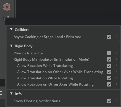
- Colliders section:
- Async Cooking at Stage Load / Prim Add
by default enabled with this option enabled, async cooking is triggered each time an asset is added to the stage, or right after a stage is loaded. Cooking pre-prepares assets for simulation.
- Async Cooking at Stage Load / Prim Add
- Avoid Changing Existing colliders (when possible)
by default disabled with this option enabled, in case an object already has a collider, clicking a button to create new collider will prefer not to change its type.
- Avoid Changing Existing colliders (when possible)
- Rigid Body section:
- Physics Inspector:
This option toggles the Physics Inspector panel.
- Rigid Body Manipulator (in Simulation Mode)
by default enabled If enabled, the transform gizmo in simulation mode is moving and rotating objects that contain a rigid body using physics force, therefore objects properly collide with each other, links are used etc. Scaling is not supported.
Refer to the toolbar section for more details.
- Rigid Body Manipulator (in Simulation Mode)
- There are additional options available.
- Allow Prim to Parent Search for Rigid Body
by default disabled If activated and the selected prim lacks a rigid body, the manipulator can traverse up the hierarchy to find a parent with a rigid body, allowing for manipulation through physics forces.
- Allow Prim to Parent Search for Rigid Body
- Allow Rotation While Translating
by default enabled allows manipulated object to rotate when translating in a selected gizmo direction.
- Allow Rotation While Translating
- Allow Translation on Other Axes While Translating
by default enabled allows translated object to be translated also on other axes than ones that were selected via the gizmo.
- Allow Translation on Other Axes While Translating
- Allow Translation While Rotating
by default enabled allows manipulated object to translate when rotating in a selected gizmo direction.
- Allow Translation While Rotating
- Allow Rotation on Other Axes While Rotating
by default enabled allows rotated object to be rotated also on other axes than ones that were selected via the gizmo.
- Allow Rotation on Other Axes While Rotating
- Info section:
- Show Floating Notifications
by default enabled you can turn off notifications when you find them too distracting. They are normally shown each time a collider is created or when physics components are removed.
- Show Floating Notifications
Mass Distribution Manipulator#
With this tool, you can easily view and potentially edit the mass attributes of a rigid body object. As an editing tool, the purpose is not to manipulate the total mass of a body; this can be done through the Mass component attributes section in the property panel (provided that the component has been added to the prim). Instead, you use the tool to define how the given mass is distributed, which is equally essential for realistic interaction with various forces and other bodies.
Note
For editing to be enabled, the rigid body must have the Mass component.
To add the Mass component to a rigid body, right click it, then pick Add > Physics > Mass. Notice that all the attributes are initially set to “Autocomputed”. In this state, NVIDIA PhysX derives the values by assuming that the mass is uniformly distributed throughout the provided geometry.
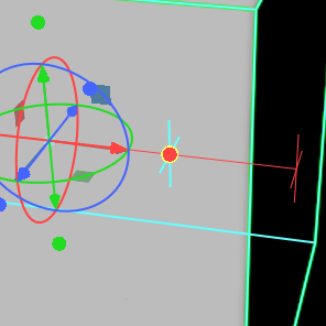
But in some cases, you might want attributes that reflect a non-uniform distribution, like when you have a car with a heavy base, which should then have a lower center of mass. You can use the Mass Distribution Manipulator to move about the center of mass by manipulating the arrows of the main gizmo to achieve this:
Sometimes, you might also have bodies where the mass is concentrated at the edges, like a metal barrel, which would result in a higher diagonal inertia than what is generated by PhysX. Or you could have a body where most of the mass is concentrated at the center, in which case the diagonal inertia should be lower. The Mass Distribution Manipulator helps you set attributes that reflect this by providing an approximation shape that you can manipulate to roughly correspond to the mass distribution of your rigid body. This approximation shape is what the cyan boxes signify.
When using the manipulator to set the diagonal inertia, aim to shape the boxes to dimensions that fit an object with mass distribution similar to your specific rigid body. You can manipulate the shape of the box in two ways. First, by using the circular handles:
This adjusts how the mass density is distributed between the edges and the center. For example, if the density is higher at the center (perhaps even because there is void at the proximities), you can move the handles closer to the center. Notice how the cyan box shrinks accordingly:
You may also want to shift more mass to the edges of the body, like if you’re making an empty crate or barrel. To do this, move the handles away from the center. Notice how a new cyan box appears at the center and expands as you move the handle outwards. This shows what inside cutout would generate the output diagonal inertia:

Note
The relative cutout size for all dimensions is always determined by the handle that is furthest away from the center.
Second, you can also rotate the shape by using the circles around the gizmo center. Setting this allows you to better fit the diagonal inertia to your concrete body:
Notice that even if it might seem rare that you can get the mass distribution manipulator shapes to match the exact physicality of your rigid body, as long as the dimensions roughly average out on something that is close, it will yield values that are good enough for most practical uses.
Physics Inspector#
Physics Inspector enables authoring single articulations and joints (or a selection) isolated from the rest of a larger simulation.
Authoring means for example: - Change the value of a joint drive in a single articulation - All the rigid bodies of that articulation get simulated, moving the articulation in the wanted position / state
Features:#
- Supported Joint Types:
Revolute Joints
Prismatic Joints
- Supported Joint API:
- Joint States API (JointStateAPI)
Position attribute (state:position)
- Joint Drives API (JointDriveAPI)
Drive Target attribute (drive:target)
Drive Velocity attribute (drive:velocity)
- Supported Joint Attributes:
- Joint Gains Attributes
Stiffness (physics:stiffness)
Damping (physics:damping)
- Joint Limits Attributes
Upper Limit (physics:upperLimit)
Lower Limit (physics:lowerlimit)
- User Interface
Multiple Panels to edit multiple articulations
Commit / Discard simulation changes
- Supports authoring:
During Simulation
Outside of Simulation
- Advanced Options:
- Simulation Options
Enable / Disable Gravity
Enable / Disable Fixed articulation base
Enable / Disable QuasiStatic mode
- Visualization Options
Show Joints Hierarchy
- Selection Helpers
Quick select all Colliders connected to a Joint
Quick select all Bodies connected to a Joint
Quick select all Joints connected to a Body
Quick select all Colliders connected to a Body
Enable the Physics Inspector#
Click the Physics Inspector checkbox under the settings of the physics authoring toolbar:
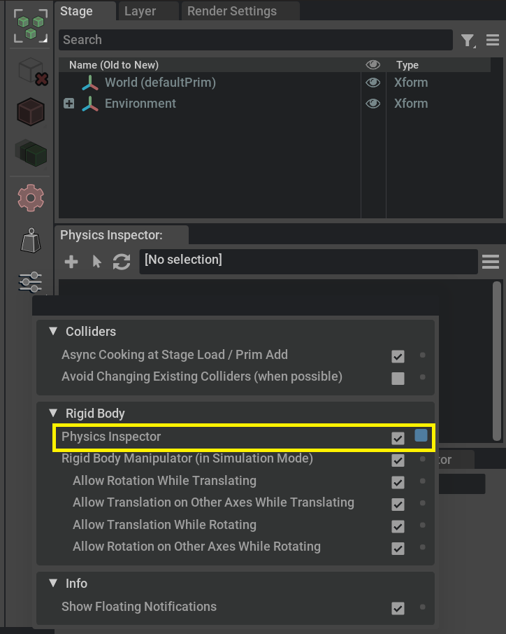
A new window named Physics Inspector appears below the stage panel.
Basic Usage Tutorial#
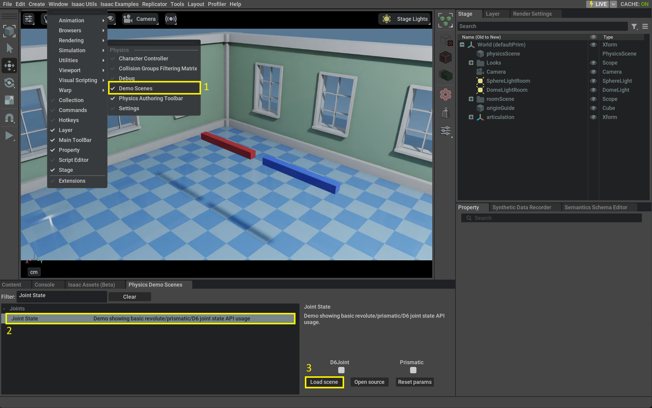
Let’s begin creating a simple revolute joint, with two colliders and a rigid body. The easiest way to do it is to load the Joint State demo.
Reach for Window > Simulation > Demo Scenes
In the Physics Demo Scenes tab search for Joint State demo, select it
Click the Load Scene button.
After enabling physics Inspector, as shown in the previous paragraph
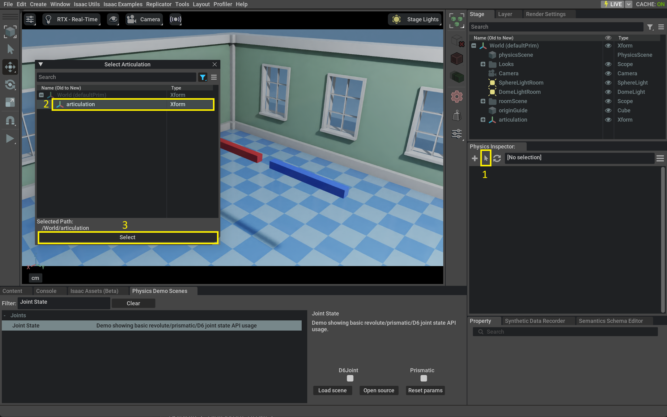
Click Select Articulation button in the Physics Inspector toolbar
Select the articulation at /World/articulation from the newly shown modal window
Press Select button at the bottom of the window
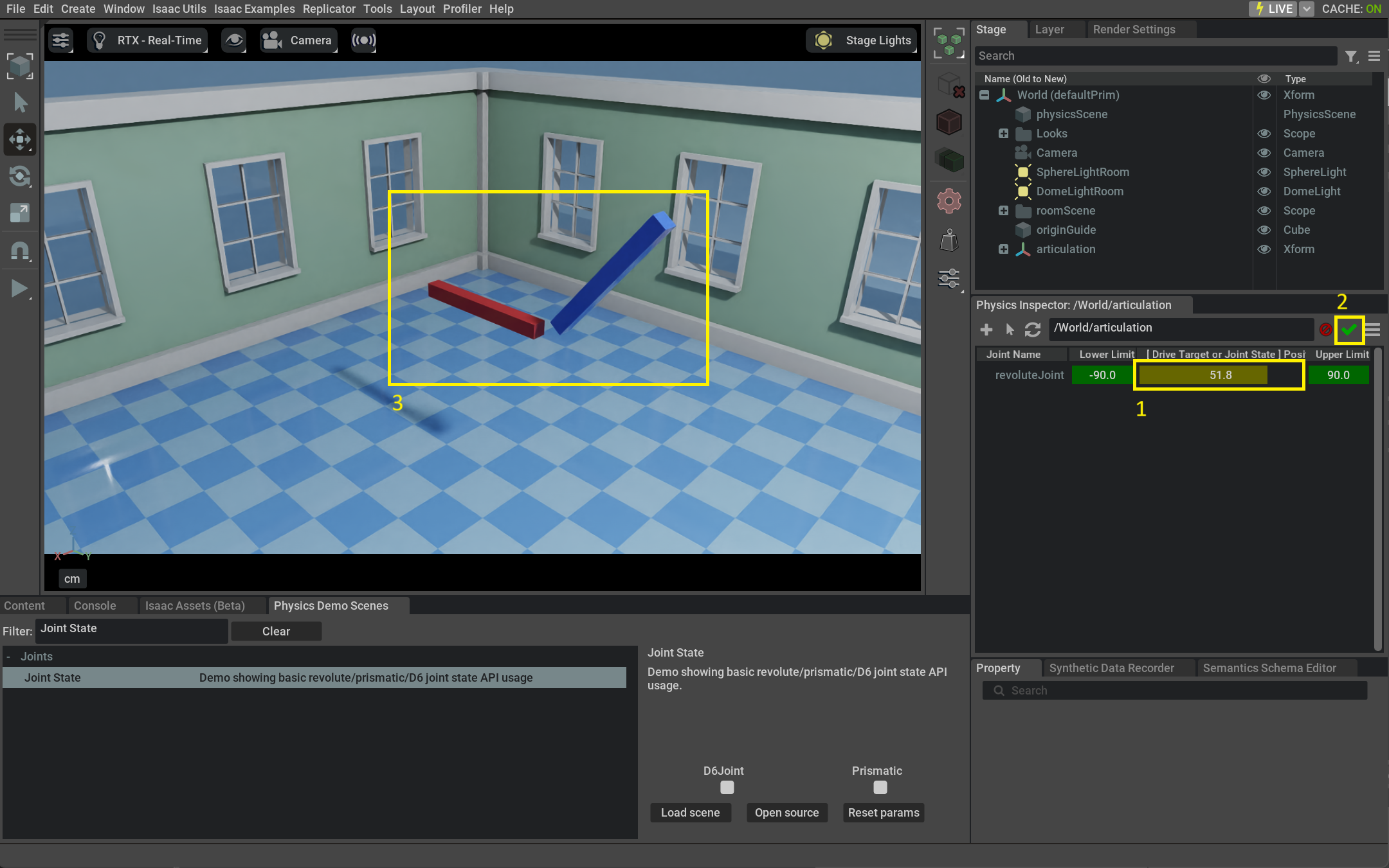
Modify the [Drive Target or Joint State Position] slider
Click the Commit Changes button (green checkmark)
The position of the blue box is now permanently modified in the stage
Toolbar#
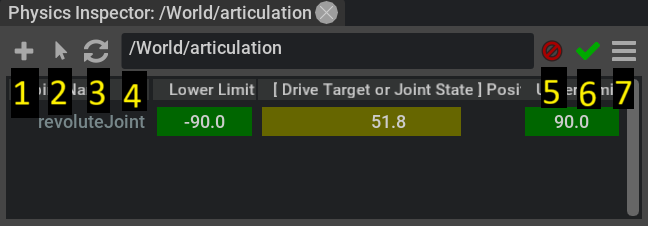
New Inspector Panel: Creates a new Inspector panel that can be later associated with an articulation or a stage selection
Select Articulation: Shows a modal popup window filtering only articulations (ArticulationRootAPI) to select one for the inspector panel
Use Selection: Associates current stage selection with the inspector panel
Current Selection: Displays the articulation or selection currently associated with the inspector panel
Discard Changes: Discards any change done by current inspector panel [Only shown if there are actual changes]
Commit Changes: Commits permanently to USD any change done by current inspector panel [Only shown if there are actual changes]
Options: Shows some advanced visualization and simulation options
Advanced Options#
Pressing the Options button shows a child menu with some more advanced entries:
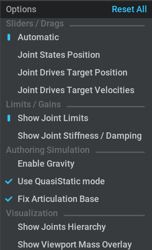
Sliders / Drags:
Automatic: Inspector will map the sliders to Joint Drive Target or Joint State Position
Joint States Position: Inspector will map the sliders to Joint State Position (instantly moves the joint to that location)
Joint Drives Target Position: Inspector will map the sliders to Joint Drives Target Position (simulates the joint from current position to target drive position)
Joint Drives Target Velocities: Inspector will map the sliders to Joint Drives Target Velocities (constant velocity of Joint Drive)
Limits / Gains:
Show Joint Limits: Two columns of the inspector modify Joints Lower and Upper limits
Show Joint Stiffness / Damping: Two columns of the inspector modify Joints Gains (stiffness / damping)
Authoring Simulation:
Enable Gravity: Controls if gravity should be enabled when running the isolated authoring simulation
Use QuasiStatic Mode: Enables the QuasiStatic mode on the Scene used for the isolated authoring simulation
Fix Articulation Base: Controls if the root node of an articulation should be fixed when authoring it (useful to avoid effects of gravity and recation forces when using drives for non-fixed articulations)
Visualization:
Show Joints Hierarchy: Shows a Tree View with the constructed joint hierarchy from parsing the ArticulationRootAPI inside omni.physx
Show Viewport Mass Overlay: Shows an overlay on the main viewport for each body part of the authoring simulation, displaying mass / intertia informations
Selection#
Physics inspector simulates only usd prims that have been associated with a window using one of the Select Articulation or Use Selection buttons. Any other prim in the scene will be excluded from the authoring simulation run by inspector.
Example:
Create or load a stage with multiple articulation
On Isaac Sim you can easily use any of the provided assets with Create >> Isaac >> Robots
Select one articulation pressing the Select Articulation button and choosing the first one from the modal dialog
Change Joint position value by using the [Drive Target or Joint State Position] sliders.
First articulation will be modified
Select a different articulation pressing again Select Articulation and choosing a different articulation from the modal dialog
Change joints by using the [Drive Target or Joint State Position] sliders.
Second articulation will be modified
Note
Selecting any USD node under ArticulationRootAPI to will extend the selection to the entire articulation in the inspector. For everything else you will have to select all joints and bodies / colliders meant to be inspected (or a common parent containing them)
Note
Inspector automatically disables itself when when Zero Gravity is enabled
Commit or Discard inspector changes#
Everytime some value is modified inside the inspector, simulation is run to update the impacted physics bodies.
If this is being done outside of regular full stage simulation, the inspector gives an option to commit (accept) or discard (cancel) simulation results.
If not explicitly committed, simulation results are automatically discarded when simulation is entered or if the inspector panel gets closed.
In this case a message is printed on the main viewport to inform the user that authoring simulation results
Note
Discarding inspector changes restores bodies position to their initial pose. Changes done to any attribute, for example joint state position / joint state drive target or to the limits is not undone.
Joint State or Drive#
The inspector can author joints that have either Joint State or Joint Drive component applied.
Authoring using Joint State position has the advantage of instantaneously setting the joint to the wanted value, accordingly positioning all bodies connected to it. Joint State is better to be used when joint gains are still not properly tuned and they define the starting joint pose for the simulation.
Joint Drive Target needs the gains for articulations to be set to a reasonable value. Authoring using Joint Target Drive makes it easier to fine tune gains to achieve the wanted behaviour. If joint gains are wrong, the bodies connected to a joint will not move or at the opposite side of the spectrum, can quickly make the simulation explode. In either case, nothing gets lost as any change done by the authoring simulation can be discarded.
In the following video:
Try modifing a complex articulation with Joint Drives, that doesn’t work
Adjust gains to make Joint Drives work
Modify the articulation again using Joint Drives. Other parts of the articulation exhibit dynamic behaviour / inertia.
Bulk add Joint State API
Modify the articulation again using Joint State. Note the absence of dynamic behaviour / inertia of other parts not being manipulated.
Note
The behaviour of the authored joint with Drive components depends on drive of damping / stiffness. If these values are not set properly, the joint may not move at all or it may oscillate indefinitely. Joint State is only supported on articulations.
Multiple Panels#
To create multiple inspector panels:
Click the Plus icon with tooltip Create new Inspector Panel
Associate the panel with any articulation or stage selection (as shown in the Selection paragraph)
The new inspector panel can be closed clicking the ‘x’ on top right corner
Note
All prims loaded in the inspector panels will be interacting (colliding) with each other.
Selection sync with stage widget#
Selection in the inspector panel is always in sync with stage selection and property widgets. For example you can select some joints in the inspector and the property widget will show all properties belonging to both of them, the same way as if they were selected in the stage widget.