Blast Destruction#
Overview#


The Omniverse™ Blast Destruction (omni.blast) extension integrates the NVIDIA Omniverse™ Blast SDK into NVIDIA Omniverse™ Kit applications. It supports authoring of destructible content, and also implements destruction in PhysX SDK-driven simulation.
Introductory Video#
User Guide#
Interface#
The Blast window is divided into panels described in the following subsections.
Fracture Controls#
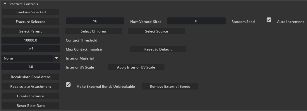
These settings are used to author destructibles from mesh prims.
Control |
Effect |
|---|---|
Combine Selected |
Combines the selected mesh prims and/or destructible instances into a “multi-root” destructible.
|
Fracture Selected |
Fracture the selected mesh prim.
|
Num Voronoi Sites |
The number of pieces in which to fracture the selected meshes.
|
Random Seed |
Seed value of pseudorandom number generator used during fracture operations.
|
Auto Increment |
If checked, the Random Seed will automatically increment after each fracture operation.
|
Select Parent |
Select the parent(s) of the currently selected chunk(s). Removes children from selection set.
|
Select Children |
Select the children(s) of the currently selected chunk(s). Removes parents from selection set.
|
Select Source |
Select the source prim associated with any part of the destructible.
|
Contact Threshold |
The minimum contact impulse to trigger a contact event with a destructible.
|
Max Contact Impulse |
Applied to kinematic destructibles, limits the force applied to an impacting object.
|
Reset to Default |
Set Max Contact Impulse back to ‘inf’ for the selection.
|
Interior Material |
The material applied to faces generated through fracture. Can be set before or after fracture and will be applied to all descendants of the selected chunk(s).
|
Interior UV Scale |
Stretch to apply to material textures on newly-created interior faces.
|
Apply Interior UV Scale |
Apply the stretch value Interior UV Scale to selected chunks.
|
Recalculate Bond Areas |
Recalculate the bond area of selected instances. Use this after scaling an instance to ensure correct areas. Bond areas are used in stress pressure calculations.
|
Recalculate Attachment |
Search for nearby static or dynamic geometry and form bonds with that geometry.
|
Make External Bonds Unbreakable |
Bonds created between a blast destructible and external geometry will never break.
|
Remove External Bonds |
Remove all bonds to external geometry.
|
Create Instance |
Creates an instance based on the selected destructible base or instance. On instances, this is equivalent to using Kit’s duplicate command on the instance prim.
|
Reset Blast Data |
Destroys fracture information, depending on the type of prim(s) selected:
Base selected - destroy all destruction info (including combine) and restores the orig mesh.
Instance selected - destroy the selected instance.
Anything else - search for chunks under selection and reset all fracture information for them.
|
Important
Fracturing operations can increase geometry counts exponentially and have the potential to overwhelm computer resources. Use caution when increasing Number of Voronoi Sites.
Instance Stress Settings#
Beginning with omni.blast-0.11, damage in Blast has been unified into a stress model simulated for each destructible instance. External accelerations applied to support-level chunks are used as input, and the solver determines the internal bond forces which are required to keep the bonded chunks from moving relative to one another. Given each bond’s area, these forces are translated into pressures. The material strength of the destructible is described in terms of pressure limits which it can withstand before breaking.
The pressure is decomposed into components: the pressure in the bond-normal direction, and pressure perpendicular to the bond normal. Furthermore, the normal component can either be compressive (if the chunks are being pushed together) or tensile (if the chunks are being pulled apart). The pressure component perpendicular to the bond normal is called shear. For each component (compressive, tensile, or shear), we allow the user to specify an “elastic limit” and a “fatal limit.” These are described in the table below.
Damage has units of acceleration, which is applied to the support-level chunk at the damage application point. If “Stress Gravity Enabled” is checked (see the table below), then gravitational acceleration is applied to each support chunk, every frame in the stress simulation. If “Stress Rotation Enabled” is checked, then centrifugal acceleration is calculated and applied to each support chunk as well.
The stress solver replaces damage shaders in older versions of Blast. Using the stress model, damage spreads naturally through the system and fracture occurs because of physically modeled limits. Impact damage is applied by translating the contact impulse into an acceleration applied to the contacting support chunk. When fractured chunk islands (actors) break free, the excess force (that which exceeded the bonds’ limits) is applied to the separating islands, which leads naturally to pieces flying off with higher speeds when the system is hit harder. The excess force and contact impulse effects are adjustable with a multiplier for each (see Residual Force Multiplier and Impact Damage Scale).
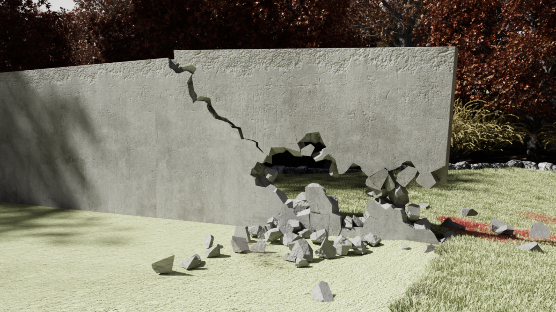
This wall has fractured under its own weight due to the pressure of the overhang jutting out to the right.#
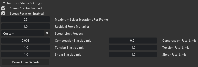
These settings are applied to the selected destructible instance(s). They control how stress is processed during simulation.
Control |
Effect |
|---|---|
Stress Gravity Enabled |
Whether or not the stress solver includes gravitational acceleration.
|
Stress Rotation Enabled |
Whether or not the stress solver includes rotational acceleration.
|
Maximum Solver Iterations Per Frame |
Controls how many passes the solver can do per frame. Higher numbers here will result in converging on a stable solution faster.
|
Residual Force Multiplier |
Multiplies the residual forces on bodies after connecting bonds break.
|
Stress Limit Presets |
Set stress limits based on various physical substances. Can be used as a rough starting point, then tweaked for a specific use case.
|
Compression Elastic Limit |
Stress limit (in megapascals) for being compressed where bonds starts taking damage.
|
Compression Fatal Limit |
Stress limit (in megapascals) for being compressed where bonds break instantly.
|
Tension Elastic Limit |
Stress limit (in megapascals) for being pulled apart where bonds starts taking damage. Use a negative value to fall back on compression limit.
|
Tension Fatal Limit |
Stress limit (in megapascals) for being pulled apart where bonds break instantly. Use a negative value to fall back on compression limit.
|
Shear Elastic Limit |
Stress limit (in megapascals) for linear stress perpendicular to bond directions where bonds starts taking damage. Use a negative value to fall back on compression limit.
|
Shear Fatal Limit |
Stress limit (in megapascals) for linear stress perpendicular to bond directions where bonds break instantly. Use a negative value to fall back on compression limit.
|
Reset All to Default |
Reset values in this panel to their defaults.
|
Instance Damage Settings#
These settings are applied to the selected destructible instance(s). They control how damage is processed during simulation.

Control |
Effect |
|---|---|
Impact Damage Scale |
A multiplier, contact impulses are multiplied by this amount before being used as stress solver inputs. If not positive, impact damage is disabled.
|
Allow Self Damage |
If On, chunks may damage other chunks which belong to the same destructible.
|
Global Simulation Settings#
These settings are general simulation settings.

Control |
Effect |
|---|---|
Max New Actors Per Frame |
Only this many Blast actors may be created per frame. Additional actors will be delayed to subsequent frames.
|
Debug Visualization#
These settings are used to visualize various aspects of a destructible.

Control |
Effect |
|---|---|
Explode View Radius |
When Not simulating, separates the chunks for inspection and/or selection.
|
View Chunk Depth |
Which chunk hierarchy depth to render while in exploded view.
|
Visualization Mode |
Controls what to render debug data for (see Visualization Mode table below).
|
Visualization Type |
Controls what debug data is to be rendered (see Visualization Type table below).
|
Visualization Mode |
Description |
|---|---|
Off |
Disable Blast debug visualization system.
|
Selected |
Only render debug visualization for the selected actor/instance.
|
On |
Render debug visualization for all instances.
|
Visualization Type |
Description |
|---|---|
Support Graph |
This shows representations of chunk centroids and bonds (drawn between the centroids). External bonds have a brown square around the bond centroid to distinguish them. The bond colors have meaning:
Green - the bond’s health is at or near its full value.
Red - the bond’s health is near zero. (Zero-health bonds are “broken” and not displayed.)
In Green -> Yellow -> Red continuum - the bond’s health is somewhere between zero and full value.
Light blue - the bond is an unbreakable external bond.
|
Max Stress Graph |
This shows the maximum of the stress components for each bond, by coloring the bond lines drawn between the centroids. The colors have meaning:
Green -> Yellow -> Red continuum - the stress is between 0 (green) and the bond’s elastic limit (red).
Blue -> Magenta continuum - the stress is between the bond’s elastic limit (blue) and fatal limit (magenta).
|
Compression Graph |
If the bond is under compression, this shows the compression component of stress for each bond. Colors have the same meaning as described for the Max Stress Graph.
|
Tension Graph |
If the bond is under tension, this shows the tension component of stress for each bond. Colors have the same meaning as described for the Max Stress Graph.
|
Shear Graph |
This shows the shear component of stress for each bond. Colors have the same meaning as described for the Max Stress Graph.
|
Bond Patches |
Render bonded faces between chunks with matching colors.
|
Debug Damage Tool Settings#
These settings control damage applied using Shift+B+(Left Mouse Button) during simulation. This is only intended for testing the behavior of a destructible.

Control |
Effect |
|---|---|
Damage Amount |
The base damage amount (acceleration in m/s^2) applied to the nearest support chunk in a destructible instance.
|
Damage Impulse |
The outward impulse applied to rigid bodies which lie within the damage radius after fracture. This is in addition to the excess forces applied by the stress solver to chunks when they break free.
|
Damage Radius |
The distance from the damage center (where the cursor is over scene geometry) to search for destructibles to damage.
|
OmniGraph Blast Node Documentation#
This section describes the Blast nodes for use in the OmniGraph system. You can find them under “omni.blast” in the “Add node” right click menu or the pop out side bar.
NOTE: The nodes automatically update the USD stage. It is possible for them to get out of sync. If that happens just save and reload the scene. That will cause the Blast data to regenerate and should get things back in sync.
Events: Flow Adapter#
The Events Flow Adapter node takes a bundle of active events and translates it into outputs that can drive Flow emitter prim attributes.
Currently only one layer is supported for all events. Work is ongoing to support visible materials mapping to Flow data via a new schema, and for Flow emitters to be able to emit on multiple layers from a single input stream of data. Then events will use material data to drive emission specific to that material.
Input |
Description |
|---|---|
events |
Bundle of events that can be processed by adapter nodes. |
Output |
Description |
|---|---|
positions |
Unique world space vectors. |
faceVertexIndices |
Indices into “positions” used to build faces. |
faceVertexCounts |
Defines how many indices make up each face. |
velocities |
Per vertex velocity. |
coupleRateSmokes |
Per vertex emission rate. |
Warning
The outputs prefixed with “subset” are not intended to be used yet. They will support multiple layers in the event bundle being passed to Flow when materials can be mapped to Flow layer IDs and Flow emitters support multiple layers.
Experimental Output |
Description |
|---|---|
subsetLayers |
Flow layer IDs referenced by faces. It is possible for their to be duplicates. |
subsetFaceCounts |
Number of faces each layer ID slot represents. Faces are grouped by layer ID. |
subsetEnabledStatus |
Tells Flow emitter if each block of faces is enabled. Allows other data to be cached. |
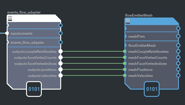
Example usage of a Flow adapter node.#
Events: Gather#
The Events Gather node takes no inputs and produces a bundle of active events. These can come from bonds breaking and contacts between objects.
Destruction events are generated for all Blast based prims when bonds break.
Collision events are reported for all prims that have the rigid body and report contacts APIs applied.
The output of this can be sent to adapter nodes to generate responses to the events.
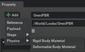
Visual materials should have the Rigid Body Material applied. This can be added by selecting the material and doing Add -> Physics -> Rigid Body Material. It is needed to report the correct materials for collision events. This is not strictly required yet, but will be when multiple materials are fully supported by this system.
Input |
Description |
|---|---|
None |
Output |
Description |
|---|---|
events |
Bundle of events that can be processed by adapter nodes. |
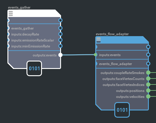
Example usage of a gather node.#
Demo Scenes#
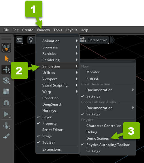
Several demo scenes can be accessed through the physics demo scenes menu option (Window > Simulation > Physics / Demo Scenes).
This will enable a Physics Demo Scenes window, which has a Blast Samples section.
Tutorials#
Getting Started#
This tutorial shows initial setup.
First enable the Blast extension (if it isn’t already):
Navigate to
Window > ExtensionsEnable the
Blast Destructionextension
You can check
Autoloadif you will be working with Blast frequently and don’t want to have to enable it by hand each time you load the applicationMake sure it says
UP TO DATEat the top of the extension details, if not, update to the latest release of the extension
Make sure there something for the mesh to interact with:
Navigate to
Create > Physics > Physics SceneAnd
Create > Physics > Ground Plane
Next, create a mesh:
Navigate to
Create > Meshand pick a mesh primitive type to create (Cube, Sphere, etc)
Be sure not to select
Create > Shape, those do not support fracture, it must be a “Mesh” type primAlternatively, you can load a mesh from another Usd source, just make sure it is a closed mesh
Set up any physics properties you want on the mesh
Right click on the mesh and navigate to
Add > Physics > Rigid Body with Colliders Presetto make it dynamic and collidableYou can then change physics properties in the
Properties > Physicspanel
Now fracture it:
Make sure the mesh to fracture is selected
Locate the Blast pane (by default it docs in the same area as Console)
Adjust Blast settings as desired (see above for what the settings control)
Click the
Fracture Selectedbutton to fracture it
This will deactivate the original mesh and select the new Blast instance container (prim named after source mesh with
__blastInstin the name)The original mesh is not altered and can be easily restored later if desired
Scrub/adjust the
Debug Visualization > Explode View Radiusin the Blast panel to review the fractureAdditional copies of the destructible can be made by clicking the “Create Instance” button in the Blast panel or running the duplicate command (
Ctrl + DorRight Click > Duplicate)
Running the simulation (by pressing Play), the destructible falls to the ground and fractures due to impact damage.
Reset Fracture#
Here we see how to undo a fracture operation:
Select the original mesh with Blast applied or the Blast base container (prim named after source mesh with
__blastBasein the name)Click the
Reset Fracture Databutton in theFracture ControlssectionDialogue will warn of deletion permanency; agree to delete
This will remove all Blast data generated and re-activate the source mesh prim
In the video we change the Num Voronoi Sites number and re-fracture.
Multilevel Fracture#
Here we see how to recursively fracture. This allows for higher overall detail with lower rendering and simulation cost by using a parent chunk for rendering and simulation until at least one child breaks off. It also allows for non-uniform fracture density throughout the mesh. Chunks of a fractured mesh may be broken down further:
Select a mesh with Blast applied
Adjust the explode view radius to make chunk selection easy
Select the desired chunk(s) to fracture further
You can also select them directly from Stage view under
<Blast base container> > chunkswhile in explode viewAdjust the
Num Voronoi Sitesin the Blast panel to the desired number
Each chunk will be split into that many pieces
Click the
Fracture Selectedbutton to fracture the selected chunksChanging the
View Chunk Depthvalue selects different hierarchy depths to displayYou may use the
Select ParentandSelect Childrenbuttons to select up and down the hierarchyRepeat as needed to get the desired level of granularity and fracture density throughout the mesh
Static Attachment#
This tutorial shows the preferred way of creating a “static” destructible, by emulating an attachment to the static world:
Create a static collision mesh
Create/load a mesh
Right click on it
Navigate to
Add > Physics > Colliders PresetCreate a destructible prim in the usual way (see Getting Started above)
Leave the source prim as dynamic, do not set to kinematic or static
Place the destructible prim adjacent to (or slightly overlapping) a static collision mesh
Select the Blast instance container prim
Set the state of
Make External Bonds Unbreakablebased on how you want the base to behave
When checked, the base pieces will remain kinematic no matter how much damage they take
This is a good idea if the Blast instance container is deeply penetrating the static geometry, otherwise physics will force them apart when the pieces become dynamic
When unchecked, the chunks can take damage and break free, becoming new dynamic rigid bodies
Press the
Recalculate Attachmentbutton to form bonds between the destructible and nearby static geometry (“external” bonds)
Debug Visualization > Visualization Type > Support Graphshows where external bonds have been formed whenDebug Visualization > Visualization Modeis set toSelectedorAll
When simulating, the bonds formed keep the destructible “static” (kinematic). When bonds are damaged, chunk islands that are not connected via bonds to static geometry become separate dynamic bodies. The chunks that remain connected to static geometry via bonds remain kinematic.
Dynamic Attachment#
Here we see how to turn a part of a rigid body into a destructible. If the rigid body consists of multiple meshes, we may select one and make it destructible:
Create an Xform prim to contain the meshes with
Create > XformCreate/load meshes and add them to the Xform container
Set the hierarchy as dynamic and collidable
Right click on the Xform prim
Navigate to
Add > Physics > Rigid Body with Colliders PresetThis will automatically set the contained meshes as colliders
Select one or more of the meshes in the container to make destructible
Click the
Fracture Selectedbutton to fracture the mesh as usualSet the state of
Make External Bonds Unbreakablebased on how you want the base to behave
The same rules apply as for Static Attachment above
Press the
Recalculate Attachmentbutton
Bonds will be formed with any adjacent or overlapping collision geometry from the same rigid Body
When simulating, the destructible mesh will move with its parent physics as a single rigid body. When bonds are damaged, chunk islands that are not connected via bonds to the parent physics geometry become separate dynamic bodies. The chunks that remain connected to the parent physics geometry via bonds remain rigidly connected to the physics body.
Note, if no bonds were formed (because there was no adjacent or overlapping collision geometry from the parent rigid body), then all chunk islands become dynamic when the destructible is fractured.
Stress Damage#
This tutorial covers the basics of the new stress damage system in Blast destruction, which is available in omni.blast-0.11. The viewer will learn how it relates to the previous damage system, how various sorts of damage are integrated within the stress framework, and how to adjust stress settings in a destructible.
Create a “wall” by first creating a mesh cube
Create menu -> Mesh -> Cube
With the new cube selected, in the property window set the Transform > Scale (x, y, z) to 5.0, 2.0, 0.2, and Translate y = 100.0
Right click on the
cube(wall)Navigate to
Add > Physics > Rigid Body with Colliders PresetCreate the destructible wall
Select the wall in the viewport
In the Blast window, under the
Fracture Controlspanel, setNum Voronoi Sitesto 1000Click the
Fracture Selectedbutton. There will be a long pause until the controls become responsive and the Cube__blastBase and Cube__blastInst prims appear in the Stage viewWith Cube_blastInst selected, press the
Recalculate Attachmentbutton to form permanent bonds between the destructible and the groundSet stress limits and debug damage amount
With Cube_blastInst selected, in the
Instance Stress Settingspanel, setCompression Elastic Limitto 0.05 andCompression Fatal Limitto 0.1In the
Debug Damage Tool Settingspanel, SetDamage Amountto 25000.0Checking
non-stressbehavior
With Cube_blastInst selected, in the
Instance Stress Settingspanel, uncheck bothStress Gravity EnabledandStress Rotation EnabledDeselect the wall (you can deselect all by hitting the Esc key). Otherwise outline drawing of the 1000-piece wall causes a large hitch
Shift+B+(Left Click) with the mouse cursor on the wall to apply damage
You can damage along the bottom of the wall, and the top will only break off when you’ve completely cut through to the other simulated
Using the full stress solver
With Cube_blastInst selected, in the
Instance Stress Settingspanel, ensure bothStress Gravity EnabledandStress Rotation Enabledare checkedDeselect the wall (you can deselect all by hitting the Esc key)
Shift+B+(Left Click) with the mouse cursor on the wall to apply damage
You can damage along the bottom of the wall, but before you cut all the way across, the stress of the overhanging piece should cause it to snap off on its own
Repeating with a weaker wall (lower pressure limits)
With Cube_blastInst selected, in the
Instance Stress Settingspanel, setCompression Elastic Limitto 0.025 andCompression Fatal Limitto 0.05Deselect the wall (you can deselect all by hitting the Esc key)
In the
Debug Damage Tool Settingspanel, SetDamage Amountto 10000.0Shift+B+(Left Click) with the mouse cursor on the wall to apply damage
Now as you damage along the bottom of the wall, it doesn’t take as large of an overhang for the stress to cause it to snap off
Note
If Shift+B+(Left Mouse Button) does not fracture a destructible, try increasing Damage Amount or Damage Radius.
Changing Material(s) requires re-fracturing.
Physics Properties of the Source Asset propagate to the fractured elements during authoring.


