Multiple Robot ROS2 Navigation#
Note
Multiple Robot ROS2 Navigation with Isaac Sim is fully supported on Linux. On Windows, Multiple Robot ROS2 Navigation with Isaac Sim could potentially produce errors.
Warning
ROS 2 Foxy is no longer tested or supported. This may result in potential issues when ROS 2 Foxy is used in conjunction with Isaac Sim 4.2 or later. ROS 2 Foxy Isaac Sim tutorial packages will be removed in a future release.
Learning Objectives#
In this ROS2 sample, we are demonstrating Omniverse Isaac Sim integrated with the ROS2 Nav2 stack to perform simultaneous multiple robot navigation.
Getting Started#
Important
Make sure to source your ROS 2 installation from the terminal before running Isaac Sim. If sourcing ROS 2 is a part of your bashrc then Isaac Sim can be run directly.
Prerequisite
Completed ROS2 Navigation for ROS2 Nav2 with a single robot. So that
ROS2 and Nav2 are installed.
ROS2 bridge is enabled.
ros2_ws(foxy_wsorhumble_ws/) is sourced so thatcarter_navigationandisaac_ros_navigation_goalare inside your workspace.
Note
In Windows 10 or 11, depending on your machine’s configuration, RViz2 may not open properly.
Occupancy Map#
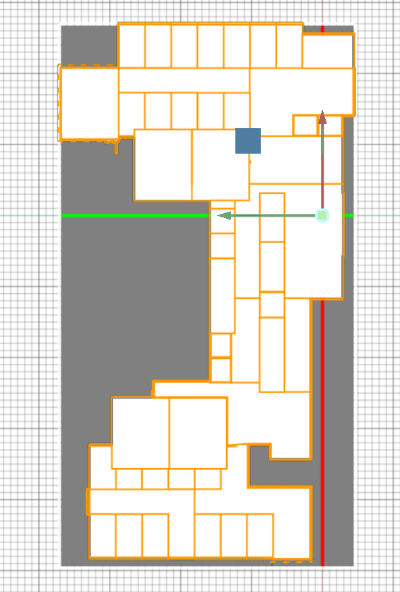
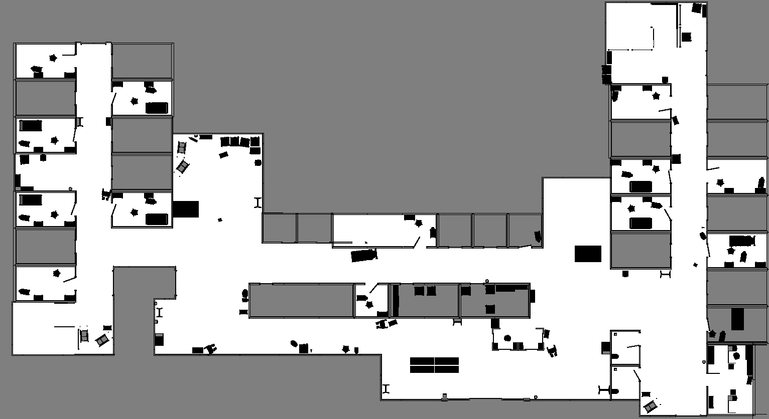
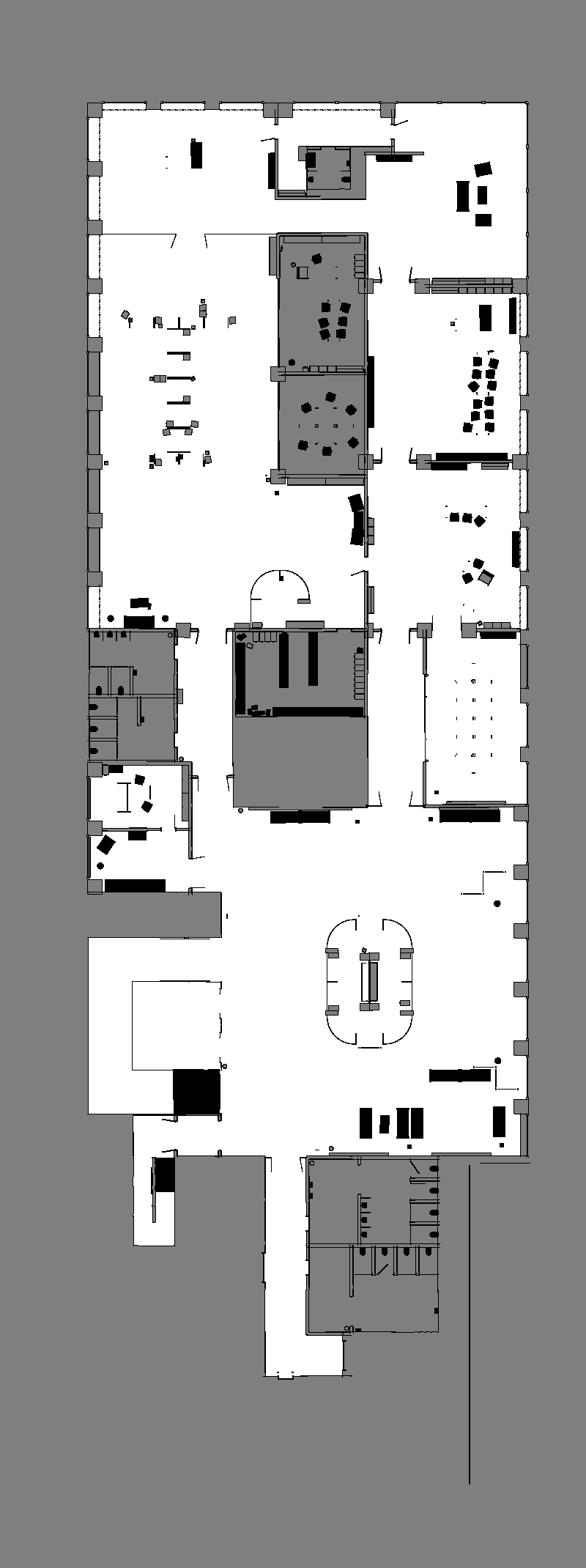
We generate the map of both the Hospital and Office environments using the Occupancy Map Generator extension within Omniverse Isaac Sim.
Follow the steps depending on which environment you would like to use.
In a new stage, go to Create -> Isaac -> Environments -> Hospital.
At the upper left corner of the viewport, click on Perspective. Select Top from the dropdown menu. Select the /Hospital prim and press F to zoom to selection. Adjust the camera view as needed.
Next, go to Isaac Utils -> Occupancy Map.
In the Occupancy Map extension, ensure the Origin is set to
X: 0.0, Y: 0.0, Z: 0.0. For the lower bound, setZ: 0.1. For the Upper Bound, setZ: 0.62. Keep in mind, the upper bound Z distance has been set to 0.62 meters to match the vertical distance of the Lidar onboard Carter with respect to the ground.Select the Hospital prim in the stage. In the Occupancy Map extension, click on
BOUND SELECTION. The bounds of the occupancy map should be updated to incorporate the selected Hospital prim.
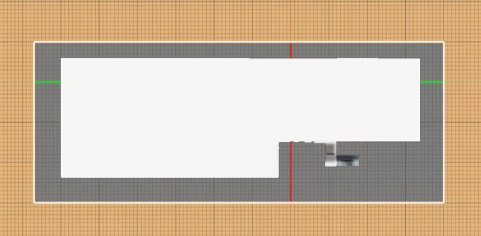
In a new stage, go to Create -> Isaac -> Environments -> Office.
At the upper left corner of the viewport, click on Perspective. Select Top from the dropdown menu. Select the /Office prim and press F to zoom to selection. Adjust the camera view as needed.
Next, go to Isaac Utils -> Occupancy Map. In the Occupancy Map extension, set the map parameters to be similar to the following image:
Once the setup for either environments is complete, click on
CALCULATEfollowed byVISUALIZE IMAGE. A Visualization popup will appear.For Rotate Image, select 180 degrees and for Coordinate Type select
ROS Occupancy Map Parameters File (YAML). ClickRE-GENERATE IMAGE. Occupancy map parameters formatted to YAML will appear in the field below. Change the image name to your preference. Copy the full text.Create a YAML file for the occupancy map parameters called
carter_hospital_navigation.yamland place it in the maps directory which is located in the samplecarter_navigationROS2 package(carter_navigation/maps/carter_hospital_navigation.yaml).Insert the previously copied text in the
carter_hospital_navigation.yamlfile.
Note
For the office environment, follow the previous steps however create a YAML file called carter_office_navigation.yaml instead.
Back in the visualization tab in Omniverse Isaac Sim, click
Save Image. Set the same image name as in the map parameters and choose to save in the same directory as the map parameters file.
An occupancy map is now ready to be used with Multiple Robot ROS2 Navigation!
Multiple Robot ROS2 Navigation Setup#
Open hospital scene by going to Isaac Examples -> ROS2 -> Multi Robot Navigation -> Hospital Scene.
For details on the ROS2 Navigation setup refer to the ROS2 Navigation Sample.
For operating multiple robots in the same environment, namespaces are utilized. This modifies the rostopic and rosnode names for different ROS2 packages, allowing for multiple instances of the same ROS2 node to run simultaneously.
To publish and receive ROS2 messages under namespaces, the node_namespace OmniGraph node found in each of the action graphs under Nova_Carter_ROS_X has been set to the corresponding robot names.
The multiple_robot_carter_navigation_hospital.launch.py and multiple_robot_carter_navigation_office.launch.py launch files found in the sample carter_navigation ROS2 package are also configured with the same robot namespaces.
Running Multiple Robot ROS2 Navigation#
Load scenario:
For the hospital environment, go to Isaac Examples -> ROS2 -> Multi Robot Navigation -> Hospital Scene.
For the Office scenario, go to Isaac Examples -> ROS2 -> Multi Robot Navigation -> Office Scene.
Click on
Playto begin simulation.In a new terminal, run the specific ROS2 launch file to begin Multiple Robot Navigation with the desired environment.
ros2 launch carter_navigation multiple_robot_carter_navigation_hospital.launch.py
ros2 launch carter_navigation multiple_robot_carter_navigation_office.launch.py
Three RViz2 windows will be launched. This process may take a few moments to startup.
In each RViz2 window, click on the Map located in the Displays panel to see the Topic name and take note of the robot namespace corresponding to the RViz2 window.
Since the positions of each robot is defined in parameter files in
carter_navigation/params/hospital/orcarter_navigation/params/office/, the robots should already be properly localized.In the
/carter1namespaced RViz2 window, click on the2D Nav Goalbutton and then click and drag at the desired location point in the map. The ROS2 Navigation stack will now generate a trajectory and the/carter1robot will start moving towards its destination!Repeat the previous step for the
/carter2and/carter3robots.
Note
The ROS2 Image publisher pipelines are disabled by default to improve performance. To start publishing images, open the _hawk action graphs found under each of the Nova_Carter_ROS prims and enable the _camera_render_product nodes. The ROS Camera publisher nodes which are downstream of the render product nodes should be enabled by default and will only start publishing when the render product node is enabled. All sensors and images in Nova Carter are being published with Sensor Data QoS. If you wish to visualize the images in RViz please expand the image tab, navigate to Topic > Reliability Policy and change the policy to Best Effort.
Troubleshooting#
This tutorial exhibits high CPU usage. If you observe instances of robots colliding or experiencing localization issues, it’s likely because the Nav2 stack is unable to properly synchronize with sensor data, resulting in missed controller commands. To improve Nav2 performance:
Try enabling the Publish Full Scan checkbox accessible through the publish_front_3d_lidar_scan OmniGraph node found in the ros_lidars action graph found under each
Nova_Carter_ROS_Xrobot.If the previous step still results in issues, also try running Isaac Sim from the terminal using the following command:
./isaac-sim.fabric.sh --reset-userImportant
The above command is experimental and not all functionality of Isaac Sim is supported there. However you might see better overall performance.
Running in python directly#
Alternatively, to load this sample environment from python directly, follow the steps outlined here.
Sending Goals Programmatically for Multiple Robots#
Note
The isaac_ros_navigation_goal package is fully supported on Linux. On Windows, running this package could potentially produce errors.
The isaac_ros_navigation_goal ROS2 package can be used to set goal poses for multiple robots simultaneously. Refer to Sending Goals Programmatically to learn about the configurations and parameters of this package.
To send navigation goals to multiple robots simultaneously, setting up node namespaces are required. In a python launch file, one way to setup namespaces is to provide a value for the namespace argument in each node object.
Set up the namespace “carter1” by defining the node using the
namespaceargument inisaac_ros_navigation_goal/launch/isaac_ros_navigation_goal.launch.py. The node object should be defined as such:navigation_goal_node = Node( name="set_navigation_goal", package="isaac_ros_navigation_goal", executable="SetNavigationGoal", namespace="carter1", parameters=[ { "map_yaml_path": map_yaml_file, "iteration_count": 3, "goal_generator_type": "RandomGoalGenerator", "action_server_name": "navigate_to_pose", "obstacle_search_distance_in_meters": 0.2, "goal_text_file_path": goal_text_file, "initial_pose": [0.0, 0.0, 0.0, 0.0, 0.0, 1.0, 0.0], } ], output="screen", )
Remember to update the map yaml file path and the initial pose of carter1 for either the hospital or office scenario.
Note
If goal generator type is set to
RandomGoalGeneratorthen a goal text file will not be used.Copy and paste the carter1 node declaration (shown in the previous step) twice and modify them for carter2 and carter3 namespaces (uniquely naming each node variable). The map yaml file path can be identical in all three nodes. Make sure to update the initial poses of carter2 and carter3.
Note
If goal generator type is set to
GoalReaderthen a separate goal text file must be created for each namespaced node.Finally at the end of the launch file, add the two newly created nodes in the launch description similar to following:
return LaunchDescription([
    navigation_goal_node,
    navigation_goal_node_2,
    navigation_goal_node_3
])
To run the newly modified launch file, use the following command:
Important
Before running the following command, ensure you have run steps 1 to 4 from Multiple Robot ROS2 Navigation Setup.
ros2 launch isaac_ros_navigation_goal isaac_ros_navigation_goal.launch.py
Summary#
In this tutorial, we covered running multiple robots with ROS2 navigation stack.
Next Steps#
Continue on to the next tutorial in our ROS2 Tutorials series, ROS2 Joint Control: Extension Python Scripting to learn how to move a manipulator using direct joint control.
Further Learning#
To learn more about Nav2 refer to the website: https://nav2.org/
Standalone python scripting version: Multiple Robot ROS2 Navigation. With this approach you have the ability to manually control the timestep and rate at which ROS components are published.


